




Solar Farm Battery Storage System: DC/AC Coupling, Curtailment and Dispatch
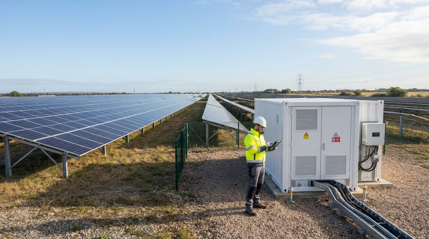
A solar farm battery storage system stores surplus solar energy and releases it later. But the value of that battery depends on three practical decisions: whether the battery connects on the DC side or the AC side, what it can realistically capture from curtailment and inverter clipping, and how the system is dispatched. This guide explains those decisions for utility-scale and large commercial solar-plus-storage projects.
What Is a Battery Storage System on a Solar Farm?
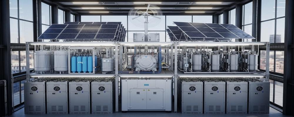
A solar farm BESS is a utility-scale battery system connected to a PV plant. The main components are battery racks or containers, a battery management system (BMS), a power conversion system (PCS), an energy management system (EMS), and grid-interconnection equipment such as transformers and switchgear.
The BESS can charge from surplus PV generation and discharge later to serve evening demand, limit export, or provide grid services. Smaller projects that combine PV and battery in one unit are usually described as a hybrid solar battery single system. This article focuses on a different scale: solar farms where the BESS is a separate, utility-scale system design.
DC vs AC Coupling: How a Solar Farm Battery Connects to the PV Plant
The most important architecture decision is where the battery connects. In a DC-coupled system, the battery connects on the PV-side DC bus. In an AC-coupled system, the battery connects on the AC side through its own PCS.
There is no universal winner. The right choice depends on whether the project is new or existing, how much PV inverter clipping or curtailment is expected, and what grid services the battery must provide.
DC-Coupled Architecture
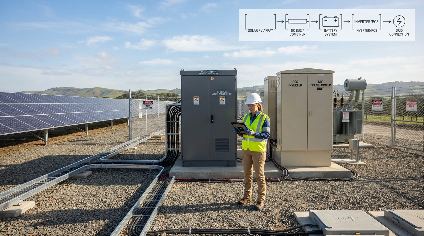
In a DC-coupled system, the PV array and the battery share a DC bus. A DC/DC converter controls battery charging and discharging before the combined energy passes through the PV inverter.
This design can absorb DC energy from the PV array that would otherwise be lost to inverter clipping. That happens when the PV array produces more DC power than the inverter’s AC rating can handle. For a new-build solar farm, DC coupling is often attractive because the PV array, inverter, and battery can be designed together.
For a deeper look at this configuration, see our dc coupled solar storage guide.
AC-Coupled Architecture
In an AC-coupled system, the PV inverter and the battery PCS connect to the AC bus separately. The battery has its own power-conversion path, so it can operate more independently of the PV inverter.
This makes AC coupling a common choice for retrofitting an existing solar farm. It also gives the battery more flexibility to provide grid services, charge from the grid, or operate when the PV plant is not generating.
DC-Coupled vs AC-Coupled at a Glance
| Factor | DC-Coupled | AC-Coupled |
|---|---|---|
| Connection point | PV-side DC bus | AC bus |
| Typical project fit | New builds designed with PV and battery together | Retrofits and projects needing battery independence |
| PV-side inverter clipping capture | Possible before the inverter | Not directly available |
| AC-side export-limit or curtailment capture | Possible with coordinated controls | Possible with coordinated controls |
| Battery operating independence | Usually limited by PV inverter capacity | Higher independence |
| Retrofit complexity | More complex | Usually simpler |
Choosing DC or AC Coupling for a Solar Farm
Use the project’s real constraints, not a default preference, to choose the architecture.
- For a new-build solar farm with significant inverter oversizing, evaluate DC coupling.
- For an existing PV plant, AC coupling is often the simpler retrofit path.
- For independent battery operation and grid services, AC coupling tends to be more flexible.
- For capturing PV energy before the inverter clips, DC coupling has an advantage.
- For reducing AC-side export curtailment, both architectures can work, but the controls and conversion steps differ.
- The final choice must also account for interconnection rules, market rules, and equipment compatibility.
Curtailment and Inverter Clipping: What a Solar Farm Battery Can and Cannot Capture
Curtailment and inverter clipping are often confused, but they are not the same problem.
Curtailment is an intentional reduction in power output, usually caused by grid congestion, low demand, or a plant’s export limit. The National Renewable Energy Laboratory describes curtailment and its causes in detail in its wind and solar curtailment report.
Inverter clipping is a physical limit. It occurs when the PV array produces more DC power than the inverter’s AC rating can handle. In that situation, a DC-coupled battery can absorb some of the excess DC energy before it reaches the inverter, as shown in Dynapower’s comparison of AC and DC coupling.
A solar farm battery can help with both problems, but it cannot eliminate them.
- The battery can charge from energy that would otherwise be curtailed or clipped, but only if it has available capacity.
- A full battery cannot absorb more solar energy.
- Some curtailment is caused by grid conditions outside the plant’s control. If the grid cannot accept the battery’s output later, the system-level constraint remains.
- The charging path must be available. This depends on the architecture, the controls, and the operating rules at the interconnection point.
Storage reduces the amount of otherwise-lost solar energy, but it does not remove every constraint on the wider grid.
Dispatch: How a Solar Farm Battery System Decides When to Charge and Discharge
Dispatch is the operating plan for the battery. It defines when the battery charges, when it discharges, and how much headroom it keeps for grid services.
The EMS coordinates dispatch with the grid operator, the site controller, the PV inverter, and the PCS. The BMS keeps the battery within safe voltage, temperature, and current limits. The PCS executes the actual power exchange.
Primary Dispatch Modes for Solar-Plus-Storage
| Dispatch Mode | Objective | Typical Control Input |
|---|---|---|
| Energy time shifting | Charge from solar surplus and discharge later | Predicted PV output, price signal, or load profile |
| Export limiting | Keep plant output within a fixed export limit | Meter reading or export cap |
| Peak shaving | Reduce peak demand or peak export | Site load or import/export meter |
| Frequency regulation | Respond quickly to grid frequency signals | Grid operator signal |
| Reserve capacity | Hold energy for a specific future obligation | Grid operator schedule or contract |
Many projects also add battery storage for frequency regulation as a secondary revenue path. The same battery can serve multiple dispatch modes, but it cannot serve them all at the same time. Discharging for one purpose reduces the energy available for another.
Who Controls Dispatch: EMS, BMS, PCS, and the Grid Operator
- The grid operator or project owner provides setpoints and constraints.
- The EMS translates those requirements into a dispatch schedule.
- The PCS controls the actual flow of power.
- The BMS protects the battery from overvoltage, undervoltage, overheating, and excessive current.
- Monitoring and SCADA systems give the operator visibility into state of charge, alarms, and system performance.
A well-designed dispatch strategy preserves enough state-of-charge headroom for obligations that arrive later in the day. It does not simply discharge whenever spot prices are high.
Sizing a Solar Farm Battery Storage System: MW, MWh, Duration, and Usable Energy
Battery sizing starts with clear definitions.
- MW measures instantaneous power. It describes how fast the battery can charge or discharge.
- MWh measures stored energy. It describes how much energy the battery can hold.
- Duration is the relationship between the two. A 20 MW battery with 40 MWh of usable energy can nominally deliver 20 MW for two hours before losses and operating limits.
- Usable energy is the part of the battery’s rated capacity that can actually be dispatched. It depends on the state-of-charge window, depth of discharge, efficiency, and degradation over time.
Sizing is not a fixed product specification. It depends on the charging opportunity, the required discharge window, the export limit, the grid services obligation, and the project’s economic case. A simple way to frame the question is this: how many hours of evening or peak delivery does the project owner need, and how much surplus solar energy is available to charge the battery before that window?
A useful example: if a solar farm regularly has 30 MWh of surplus energy that would otherwise be curtailed, and the owner wants to deliver it over a three-hour peak window, the battery needs at least 30 MWh of usable capacity and a charging path that can accept that energy before the discharge window begins. Actual sizing also requires engineering analysis of PV output, inverter limits, export constraints, and battery degradation.
Key Equipment and Integration Requirements for a Solar Farm BESS
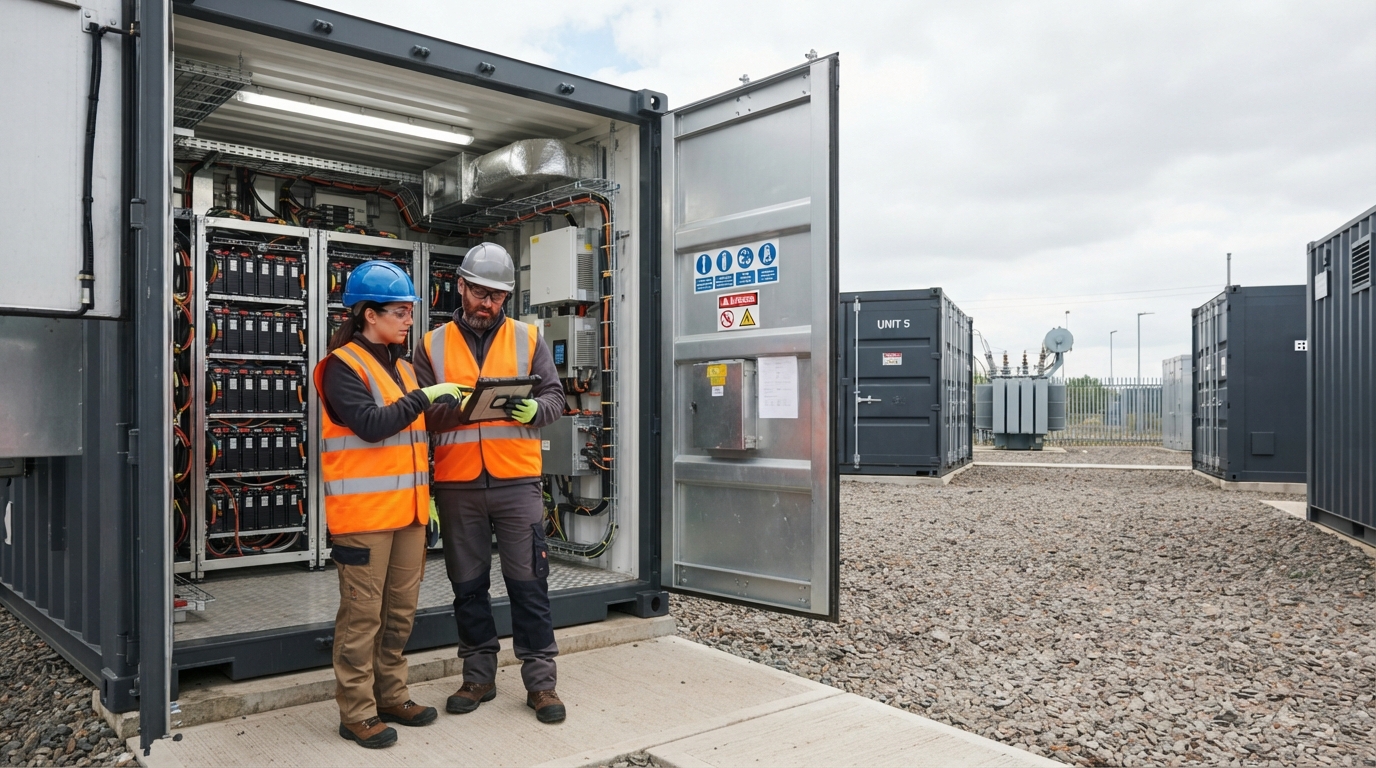
A solar farm BESS is more than a set of battery modules. The complete system includes the battery enclosure, power conversion, controls, thermal management, safety equipment, and grid-interface infrastructure.
| System Component | Role |
|---|---|
| Battery racks, cabinets, or containers | House the battery modules and provide physical and thermal protection |
| Battery management system (BMS) | Monitors cell voltage, temperature, and current; manages balancing and protection |
| Power conversion system (PCS) | Converts DC battery power to grid-compatible AC power and manages charging |
| Transformer and switchgear | Connect the BESS to the solar farm collection system or utility grid |
| Energy management system (EMS) | Coordinates PV generation, battery charging, discharging, and grid instructions |
| Thermal management | Controls battery temperature using air cooling, liquid cooling, or both |
| Fire detection and suppression | Detects overheating events and limits their impact |
| Monitoring and SCADA | Provides operational visibility, alarms, and data logging |
Containerized configurations are common at solar-farm scale because they pre-integrate battery racks, cooling, controls, and safety equipment into one deliverable. For an example of that packaging, see VoltaLink’s solar hybrid battery container.
Thermal management and fire safety must be project-specific. Air cooling is simpler, while liquid cooling can be more effective in high-power or high-temperature applications. The correct choice depends on climate, container design, system size, and project configurational requirements. Never assume that one cooling method is right for every site.
Procurement and Supplier Evaluation Checklist
A solar-farm BESS procurement is a technical buying decision. The reader should evaluate suppliers using the same rigor they would use for any major power-plant asset.
- Ask for model-specific datasheets that clearly show voltage (V), current (A), amp-hour capacity (Ah), power (kW), and energy (kWh).
- Request a single-line diagram showing how the BESS connects to the PV plant and the grid.
- Confirm which certificates and standards apply to the exact model being offered and to the project’s jurisdiction.
- Ask about the cooling method. Do not assume a liquid-cooled product is the same as an air-cooled product.
- Confirm the fire detection and suppression design, including how it is activated and who maintains it.
- Verify PCS, EMS, BMS, and inverter compatibility with the site’s existing or planned equipment.
- Confirm which communication protocols are supported and how the BESS will interface with the plant controller or SCADA.
- Clarify the commissioning scope. Who installs, tests, and commissions the system?
- Review warranty terms and degradation assumptions. Battery performance changes over time, and the warranty should reflect that.
- Ask whether the supplier provides a complete BESS or only the battery modules.
Choosing the Right Solar Farm Battery Storage Approach
There is no one-size-fits-all answer. The right solar farm battery storage system depends on the project’s curtailment profile, whether the plant is new or existing, the dispatch objectives, and the grid interconnection rules.
A practical next step is to document those project constraints and then compare architectures and suppliers against them. If you are defining a solar-farm BESS requirement, VoltaLink can help you translate those constraints into a system design as a battery and energy-storage system manufacturer/exporter.

-

 OEM Residential Energy Storage Solutions: Passive vs. Active Cell Balancing
2026-09-30
-
 Smart Home Battery with BMS Communication: Cybersecurity and BMS Safety
 -
 10kWh Home Battery Backup System: Is 90% DoD Better for Daily Solar Storage?
2026-09-29
-
 Integrated Home Energy Storage System 150–430V MPPT Design
2026-09-28
-
 LiFePO₄ Residential Backup Battery SOC Accuracy in Parallel Systems
Share this:





.svg)






-899.svg)


