




BESS Container Site Layout: Access, Spacing, Cabling and Expansion
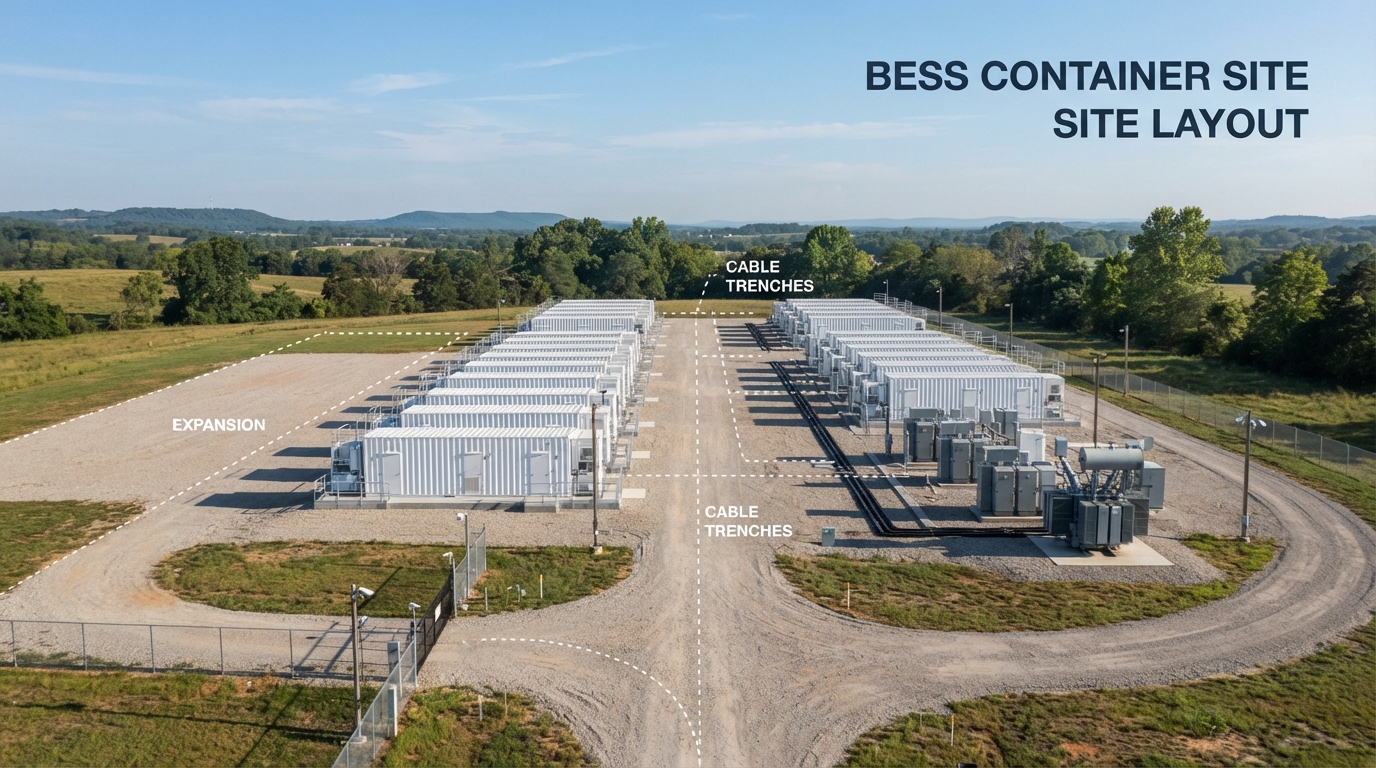
A BESS container site layout is the arrangement of battery containers and balance-of-plant equipment—power conversion systems, transformers, switchgear, controls, and auxiliary systems—on a defined project site. The layout determines whether the system can be delivered, operated, maintained, protected, and expanded without costly redesign. For a broader introduction to containerized battery storage, see our guide on Battery Energy Storage Container: Smart Energy Control for Real-Time Grid Response.
This guide covers the planning sequence for a preliminary BESS container site layout. Final clearances, foundation loads, and code compliance must be confirmed with the equipment manufacturer, the project engineer, and the local authority having jurisdiction (AHJ).
What a BESS Container Site Layout Includes
A complete BESS site layout positions more than just the battery containers. The following elements all need space on the site plan:
- Battery containers housing the battery racks, BMS, thermal management, and fire detection and suppression equipment.
- Power conversion systems (PCS/inverters) that convert between battery DC power and AC power.
- Transformer and medium-voltage (MV) switchgear area for grid interconnection.
- Control and monitoring location for EMS/SCADA, communications, and metering.
- Auxiliary power, fire water supply, and other support systems.
- Access roads, turning areas, fencing, gates, lighting, and drainage infrastructure.
Each block has its own spatial, safety, and maintenance requirements, so the layout must be developed as one coordinated plan rather than as independent equipment positions.
Before You Draw: Inputs That Shape the Layout
Before placing a single container on the plan, gather the project inputs that drive the layout:
- Rated power (MW/MVA AC) and energy capacity (MWh).
- Operating profile: peak shaving, load shifting, backup, frequency response, or solar firming.
- Point of grid connection and voltage level.
- Site boundary, available land area, topography, and existing underground services.
- Ground conditions, including the need for a geotechnical investigation.
- Elevation, flood risk, drainage pattern, and environmental constraints.
- Local zoning and planning restrictions.
- Future expansion plans, even if only tentative.
- Cooling architecture (air-cooled or liquid-cooled), because it affects auxiliary equipment and service clearance.
These inputs determine the number of containers, the size of the PCS and transformer, and the site area required. A layout developed without them will almost certainly need rework.
Arranging the Equipment Blocks
The layout process moves from project inputs to equipment blocks:
- Place battery containers in rows or blocks with a consistent orientation so that door access, cooling airflow, and maintenance routes remain predictable.
- Position PCS/inverters as close to the battery containers as practical, because long DC cable runs increase cost, losses, and protection complexity.
- Locate the transformer and MV switchgear near the grid-connection point to minimize medium-voltage cable length.
- Place control and auxiliary equipment where it is accessible but not exposed to the highest-risk zones of the site.
- Account for the difference between utility-scale and commercial/industrial projects. A utility project typically uses more containers, a separate PCS and transformer area, and a dedicated substation interface. A commercial or industrial deployment may use fewer containers and a more integrated power-conversion architecture. For application context, see our guide on ci energy storage system.
The goal is a logical flow from the battery blocks to the power-conversion area, then to the transformer and grid interface, with access and cable routes planned around those relationships.
Planning Access and Maintenance Routes
Access is often treated as an afterthought, but it should be one of the first constraints applied to the layout. Every container door, cooling unit, fire panel, and cable trench must remain reachable after the site is complete.
Three Types of Access Every Layout Needs
- Delivery access: The container transport route, gate width, turning radius, and temporary cranage and offloading area must all fit within the site.
- Routine maintenance access: Technicians need room to open doors, service HVAC filters, inspect fire-suppression equipment, and reach cable terminations.
- Emergency access: Fire-service approach routes, water-supply connections, and turnout areas must remain clear and operable at all times.
These three access types have different vehicle sizes, surface requirements, and clearance needs. A road that works for a delivery truck may not serve a fire appliance, and a maintenance path may be too narrow for either. Placement near site boundaries can also require acoustic review; our guide on bess container noise levels covers that consideration in more depth.
BESS Container Spacing and Setbacks
Container spacing is the most common source of confusion in BESS site planning. There is no universal distance between battery containers that can be applied to every project. The required separation depends on:
- The exact battery system model and enclosure design.
- The cooling architecture and ventilation requirements.
- Fire-test evidence for that specific system.
- The adopted installation code and its edition in the project jurisdiction.
- The AHJ’s assessment of the proposed fire-safety design.
Where NFPA 855 has been adopted, its provisions for stationary energy-storage systems provide the relevant installation framework. Fire-propagation data from UL 9540A testing, explained by UL Solutions, can also inform separation and fire-protection decisions. However, these sources do not produce one universal clearance value; they produce requirements and allowances that apply to specific systems and projects. The manufacturer’s installation manual for the selected model must state its own clearance requirements.
Setbacks to site boundaries, buildings, and public exposures are a separate consideration from container-to-container spacing. Zoning rules, fire codes, and the AHJ all play a role in determining how far the equipment must sit from the property line.
For this reason, a responsible layout plan treats spacing as a project-specific engineering decision, not a fixed number copied from another project.
Foundations, Drainage and Civil Interfaces
The site layout must be coordinated with the civil design before the foundation is ordered:
- Battery containers and PCS/transformer blocks require engineered foundations designed for their weight, anchorage, and ground conditions.
- The layout must account for foundation size and load distribution; soil bearing capacity and settlement characteristics come from the geotechnical investigation.
- Containers with bottom cable entry require the foundation and cable trenches to be coordinated before the pad is poured.
- Drainage and grading must prevent water from pooling around foundations, cable entries, or equipment pads.
- Flood exposure and site elevation affect both equipment placement and the design of underground cable routes.
Foundation design is a subject of its own. For a detailed treatment of the structural and civil requirements, see our article on bess container foundation requirements. From a layout perspective, the key is to treat the foundation as part of the equipment block, not as an invisible line beneath it.
Designing Cabling and Cable Routes
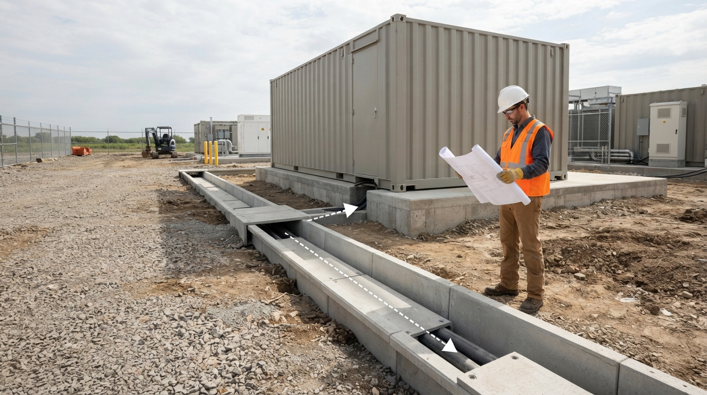
Cable routing is a layout driver, not a final detail. The site plan must reserve space for several cable families:
| Cable type | Purpose | Layout implication |
|---|---|---|
| DC cabling | Connects battery containers to PCS | Should be as short as practical; affects losses and protection |
| AC/MV cabling | Connects PCS to transformer and grid | Route length affects voltage drop, cost, and thermal design |
| Auxiliary power | Powers controls, cooling, lighting, security | Must reach all equipment blocks |
| Grounding/earthing | Bonds all equipment for safety | Follows the entire site layout |
| Communications/SCADA | Carries control and monitoring signals | Must reach BMS, PCS, EMS, and grid-interconnection equipment |
Cable trenches, duct banks, or above-ground cable trays must be planned as corridors through the site. They cannot cross roads, future expansion zones, or equipment foundations without structural and civil coordination. Cable bend radius must be respected at entry points, and cable length must be checked for voltage drop and ampacity—especially on long MV or DC runs.
The relationship between the layout and the cable route works in both directions: equipment positions define where cables must go, and cable routes can constrain where equipment can be placed.
Fire Safety and Emergency Access
Fire-safety considerations affect the layout at the earliest stage. Battery systems carry an inherent thermal-runaway risk, and the site layout must support detection, suppression, and emergency response.
Key layout-related fire-safety checks:
- Maintain fire-service access routes and water-supply connection points.
- Keep container spacing and setbacks consistent with the selected system’s fire-test evidence and the applicable installation code.
- Ensure fire detection and suppression equipment—whether container-integrated or site-level—remains serviceable and reachable.
- Coordinate with the AHJ early, because local requirements may impose conditions that differ from the manufacturer’s general guidance.
The U.S. Environmental Protection Agency has published practical guidance on BESS installation and incident response, and NFPA 855 provides an installation standard where it has been adopted. These references reinforce the same point: fire-safety provisions are system-specific and jurisdiction-specific, and they must be verified before the layout is finalized.
Planning for Future Expansion
A good layout leaves room for growth even when the first phase does not require it. Expansion planning means:
- Reserving land for additional battery containers and PCS units.
- Keeping future expansion zones clear of cable trenches, drainage features, and access routes that would have to be moved.
- Oversizing switchgear, transformer capacity, and control architecture where the cost is justified by likely future phases.
- Leaving spare cable ducts or defining a cable corridor that can carry future feeders.
- Designing access so that new equipment does not block service routes for existing units.
The exact expansion margin depends on the project’s business case and the supplier’s system architecture. It should be discussed with the supplier and engineer before the land is committed.
BESS Site-Layout Review Checklist
Before the preliminary layout proceeds to detailed design, run through this checklist:
- Project inputs—power, energy, duration, grid connection, site boundary, constraints, expansion intent—are documented.
- Battery containers, PCS, transformer, switchgear, controls, and auxiliary equipment are all shown.
- Delivery access and temporary cranage areas are feasible.
- Routine maintenance access to all service points is provided.
- Emergency/fire-service access and water supply are preserved.
- Container spacing and setbacks are based on model-specific documentation and AHJ review.
- Foundations, drainage, elevation, and cable-entry points are coordinated.
- DC, AC/MV, auxiliary, grounding, and communications cable routes are planned, segregated, and protected.
- Cable route lengths have been checked for voltage drop and ampacity.
- Expansion zones and spare ducts are protected.
- Supplier manuals, drawings, single-line diagram, certificates, and O&M documents have been requested.
Questions to Ask Your BESS Supplier Before Finalizing the Layout

The supplier is the primary source for several layout-critical details. Before the layout is locked, request:
- General arrangement drawing with dimensions and door/service locations.
- Foundation loads, anchorage details, and allowable tolerances.
- Cable entry locations and trench requirements.
- Required clearances for ventilation, maintenance, and fire safety.
- HVAC/cooling and auxiliary power requirements.
- Single-line diagram and electrical interface details.
- Communications and control integration documentation.
- Certificates and test reports for the exact model.
- O&M, commissioning, and emergency-response documentation.
These documents turn a conceptual layout into a design that can be reviewed by the engineer and the AHJ. If a supplier cannot provide them for the specific model, the layout has not been validated. If you are evaluating vendors, our page on bess container supplier may be a useful starting point.
Common BESS Container Site-Layout Mistakes
Watch for these recurring errors:
- Assuming a universal container spacing value instead of using the model-specific manual and AHJ review.
- Blocking container doors or service panels with other equipment.
- Placing the transformer far from the grid connection, creating excessive MV cable runs.
- Routing cables through future expansion zones.
- Forgetting delivery and cranage access until after the layout is fixed.
- Treating a product manual as a substitute for local code and AHJ approval.
- Ignoring drainage or flood exposure at cable trenches and foundations.
- Underestimating the clearance needed for routine maintenance and emergency response.
A preliminary BESS container site layout is the bridge between the system concept and the engineered project. Start with the project inputs, arrange the equipment blocks, then resolve access, spacing, civil coordination, cabling, fire safety, and expansion as one connected plan. If you are evaluating suppliers or need application-specific guidance, compare the documentation requirements above with what each vendor can provide.

-

 OEM Residential Energy Storage Solutions: Passive vs. Active Cell Balancing
2026-09-30
-
 Smart Home Battery with BMS Communication: Cybersecurity and BMS Safety
 -
 10kWh Home Battery Backup System: Is 90% DoD Better for Daily Solar Storage?
2026-09-29
-
 Integrated Home Energy Storage System 150–430V MPPT Design
2026-09-28
-
 LiFePO₄ Residential Backup Battery SOC Accuracy in Parallel Systems
Share this:






.svg)






-899.svg)


