




Battery Storage for Factories: Peak Control, Backup and Solar Self-Use
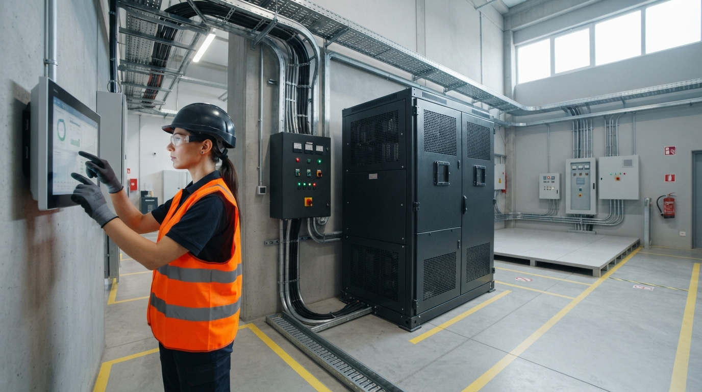
Battery storage for factory sites is an energy-storage system installed at an industrial facility — not a factory that makes batteries. It stores electricity from the grid or from on-site solar and releases it when it delivers the most value: during demand peaks, outside solar production hours, or when the grid supply fails.
A factory battery is more than a stack of cells. A complete system includes battery modules, a battery management system (BMS), power conversion, an energy management system (EMS), protection devices, and monitoring. Together, these components give a factory three practical capabilities: peak control, solar self-use, and backup for critical loads.
These capabilities are part of the wider commercial and industrial energy-storage category. VoltaLink’s Comprehensive Guide to Commercial & Industrial Energy Solutions covers the broader picture. This guide focuses on what factory decision-makers need to evaluate before selecting a battery system.
What Factory Battery Storage Can Do
Before sizing a system, it helps to understand the four jobs a battery can perform at a factory. Most projects start with one primary job and add others later.
| Use case | What the battery does | Main design driver | Where the value comes from |
|---|---|---|---|
| Peak shaving | Discharges during short demand peaks to keep grid demand below a target | Power rating (kW) and energy capacity (kWh) for the peak duration | Lower demand charges |
| Load shifting | Charges when electricity is cheaper, then discharges when it is expensive | Energy capacity (kWh) and EMS scheduling | Lower energy costs |
| Solar self-use | Stores surplus rooftop solar and discharges after the sun drops | Solar surplus profile and evening or night load | Higher self-consumption, less exported energy |
| Backup power | Supports selected critical loads during a grid outage | Critical-load kW, usable kWh, and outage duration | Production continuity |
A factory can also use storage in a microgrid or alongside a diesel generator, but those configurations normally build on one of the four functions above.
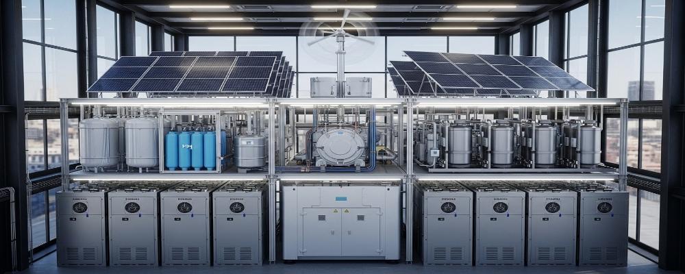
To see how these pieces work together, VoltaLink’s commercial and industrial energy page illustrates a site with 200 kWh of lithium-ion storage, a 50 kW solar array, and EMS-based load management. The figures are an example, not a template: every factory needs its own load-based sizing study.
Peak Control: Reducing Demand Peaks and Demand Charges
Peak control is usually the first reason a factory buys a battery. Production sites create demand spikes when several machines start at once, a large compressor switches on, or lines accelerate after a break. Many utility tariffs measure the highest demand in a short interval — often 15 or 30 minutes — and turn that number into a demand charge that appears on bills for months afterward.
A battery trims that peak by discharging during the critical interval. The power rating needed is the kW reduction the factory wants to achieve. The energy needed is that kW reduction multiplied by the duration of the peak.
Factory peaks often last only a few minutes, which makes them a good fit for batteries: the system is used for a short time even though the financial effect extends across the year.
For a deeper look at tariff mechanics and control logic, see battery storage for peak shaving.
How Peak Control Works
The operating sequence is straightforward:
- A meter or the EMS monitors the factory’s grid demand in real time.
- When demand approaches a set threshold, the battery discharges to cover the excess.
- When demand falls below the threshold, the battery stops discharging.
- The battery recharges from solar or the grid when spare capacity is available.
The EMS can use a fixed threshold or forecast logic based on historical interval data. Either way, the battery is not powering the entire factory. It is subtracting power so that grid demand stays below the target.
Peak Shaving versus Load Shifting
Peak shaving is often confused with load shifting, but they are different operating strategies.
| Peak shaving | Load shifting | |
|---|---|---|
| Primary goal | Reduce the demand peak | Move energy consumption to another time |
| Trigger | Demand approaching a threshold | Time-of-use price or demand period |
| Battery action | Discharge during the peak event | Charge in low-cost hours, discharge in high-cost hours |
| Economic value | Lower demand charges | Lower energy costs |
Both strategies can run on the same system, but the EMS needs to know which one matters most at each moment.
Solar Self-Use: Storing Factory Rooftop Power
Factories with rooftop solar face a familiar mismatch: the sun shines in the middle of the day, while the factory may run at full capacity in the morning and evening. When the solar array produces more than the factory consumes, the surplus is exported to the grid — often at low value, or not at all.
A battery solves that problem. Surplus solar charges the battery instead of flowing back to the grid. Later, when production continues after sunset or starts before sunrise, the stored energy is used on site. The factory needs less grid energy and extracts more value from panels it has already installed.
The value of this mode depends on several site-specific factors:
- How much surplus solar the factory generates on weekdays and weekends.
- Whether the factory operates at night or has a morning peak before the sun rises.
- How the local utility treats solar exports and net metering.
- How much of the site’s load can practically align with solar production.
The EMS plays a central role. It can prioritize charging from solar while holding back a reserve for peak shaving or backup, so the battery is not empty when an outage or demand spike arrives.
Backup Power: Protecting Critical Factory Loads
The third use case is backup power. A grid outage at a factory can stop a production line, crash a control system, or leave pumps and safety systems without power. A battery can handle these events, but it is not usually sized for the entire plant.
Whole-factory backup would require enough power for every motor, heater, and process that could run at once, plus enough energy for the entire outage. For most sites, that is uneconomical. The practical approach is to identify a small group of critical loads and keep them running.
For a broader view of outage protection in commercial and industrial settings, see commercial backup energy storage solutions.
Critical Loads versus Whole-Factory Backup
The critical load list must come from the factory’s own operations, not from a generic template. Typical candidates include:
- Programmable logic controllers and process control systems.
- Server and IT equipment that supports production management.
- Safety lighting, alarms, and security systems.
- Pumps, compressors, or small process lines that must continue running.
- Charging stations for electric forklifts, if they support material flow.
Each load is defined by its power draw, its runtime, and how quickly it must be restored after an outage. Those three values determine how much of the battery’s capacity is consumed.
Backup Runtime and Reserve
Runtime is not determined by the nominal battery size on a datasheet. What matters is usable energy — the energy the battery can deliver after depth-of-discharge limits and reserve settings are applied.
A simple planning estimate is:
Approximate runtime (hours) = Usable energy (kWh) ÷ Average critical load (kW)
For example, a battery with 200 kWh of usable energy supporting an average critical load of 50 kW would provide roughly four hours of runtime. Actual runtime will be lower because inverter losses, battery condition, and load variation all reduce what reaches the equipment.
A reserve setting in the EMS protects part of the battery for outage response. The same system can then perform peak shaving or solar self-use without risking the backup function.
Where a factory already operates a diesel generator, a battery can cut fuel use and improve response time. The hybrid configuration is covered in bess for diesel generator optimization.
Sizing a Factory Battery: Power, Energy and Runtime
Battery sizing starts with two numbers: kW and kWh. They are often treated as interchangeable, but they answer different questions.
- kW determines what the battery can power at a single moment. Shaving a 150 kW demand peak requires at least 150 kW of discharge power.
- kWh determines how long it can deliver that power. A 150 kW load running for 30 minutes needs 75 kWh of usable energy, plus losses.
- For solar self-use, sizing follows the surplus solar profile and the load that must be covered after sunset.
- For backup, sizing follows the critical load in kW and the required runtime in hours.
The U.S. Department of Energy’s Federal Energy Management Program publishes a BESS evaluation method that describes how battery capacity, power, and performance should be assessed in a structured way.
kW and kWh Must Be Sized Together
A battery can have plenty of power but too little energy, or plenty of energy but too little power. Both conditions fail at the moment the system is needed.
| Sizing input | Example value | What it means for the battery |
|---|---|---|
| Critical load | 100 kW | The battery must deliver at least 100 kW |
| Required runtime | 2 hours | The battery must deliver at least 200 kWh of usable energy |
| Peak to shave | 180 kW for 15 minutes | The battery needs 180 kW discharge and about 45 kWh for the event |
| Solar surplus | 120 kWh per day | The battery should hold the surplus and discharge it during the night |
These inputs produce very different system sizes. A battery sized only for a short peak may be useless for a multi-hour outage, and a battery sized for long backup may be needlessly expensive if the real problem is a 15-minute demand spike.
Data Needed for a Factory Sizing Study
A credible supplier will base a proposal on site-specific data, not on a generic estimate. The factory should prepare:
- Interval electricity data — ideally 15- or 30-minute readings for at least 12 months.
- Monthly demand peaks and the times when they occur.
- Production schedule, including shifts, weekends, and seasonal changes.
- Solar system size, orientation, and daily generation profile.
- A list of critical loads and the required outage duration for each.
- Site constraints, including available space, switchboard details, transformer capacity, and environmental conditions.
Better data produces a better battery size and reduces the chance of paying for capacity the factory does not need.
System Architecture: From Battery Cells to the Factory Switchboard
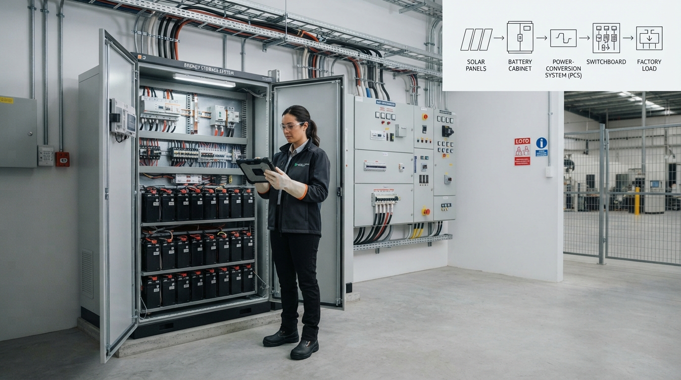
A factory battery system is built in layers. Battery cells are grouped into modules, then into racks. The racks are installed in an enclosure — an indoor cabinet or an outdoor container — that provides mechanical protection, thermal management, and fire-safety integration.
The battery itself is only one component. The BMS protects the cells and handles balancing. The PCS or inverter converts battery DC power to the AC power used by factory equipment. The EMS decides when to charge, discharge, and hold energy in reserve. Together, they form what is usually called a battery energy-storage system (BESS).
For an overview of how VoltaLink presents complete commercial and industrial systems, see ci energy storage system.
BMS, PCS and EMS: Different Jobs, All Required
These three components are often confused.
| Component | Full name | Role in the system |
|---|---|---|
| BMS | Battery management system | Monitors voltage, temperature, and current; balances cells; prevents overcharge, deep discharge, and overheating |
| PCS | Power conversion system | Converts DC power to AC power; manages grid and load connection |
| EMS | Energy management system | Controls charge and discharge timing, reserve levels, and interaction with solar, grid, and factory loads |
The components must communicate. Common interfaces include CAN, RS485, and Ethernet, but the exact protocols and inverter compatibility must be confirmed for the system being proposed.
Where the Battery Connects to the Factory Electrical System
The battery is not a plug-in appliance. It connects to the factory’s low-voltage switchboard, or to a dedicated transformer for larger systems.
- Metering and current transformers may be needed so the EMS can see real-time load.
- Protection settings must coordinate with existing switchgear.
- Grid-connected systems may require anti-islanding protection so the battery disconnects safely if the grid fails.
A qualified electrical engineer should review the connection design before purchase.
Cabinet or Container? Choosing the Right Battery Format
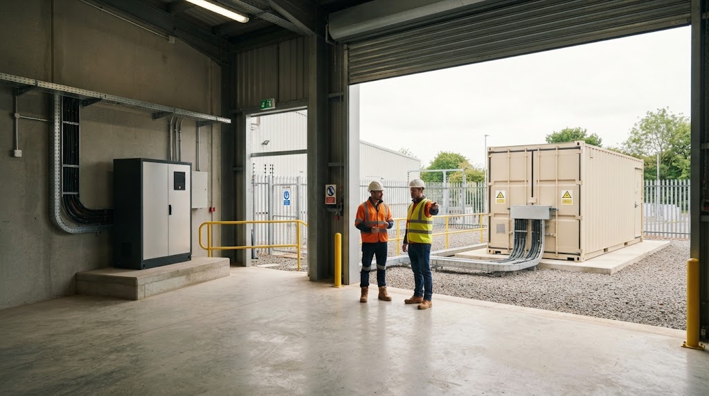
Factory systems are usually delivered as a cabinet or as a containerized system. The choice affects installation, cooling, expansion, and fire-safety planning.
| Consideration | Cabinet BESS | Containerized BESS |
|---|---|---|
| Typical size range | Smaller to mid-size | Larger energy capacity |
| Installation location | Indoor or outdoor, depending on rating and fire codes | Usually outdoor |
| Cooling approach | Air or liquid, depending on design | Integrated cooling system |
| Fire-safety design | Site-dependent | Engineered as part of the container |
| Expansion | Modular additions | Larger single system |
A cabinet format works well when space is limited or the factory prefers an indoor solution. A container is common when the site needs higher energy capacity or when outdoor placement reduces fire-safety complexity inside the building.
VoltaLink’s containerized energy-storage system page describes this approach for industrial and large-scale projects. The format decision should follow the load study, not a preference for a particular enclosure.
Installation, Safety and Grid Connection
A factory battery stores significant energy and moves high power through cables. It must be installed by qualified engineers and licensed electrical contractors, and it must satisfy local electrical and fire-safety requirements.
Standards such as NFPA 855, UL 9540, UL 9540A, and IEC 62933 provide frameworks for safe installation, testing, and fire mitigation in different markets. The U.S. Environmental Protection Agency publishes guidance on safe installation and incident response for battery energy-storage systems, and its BESS fact sheet outlines the main safety considerations for installers and emergency responders. Sandia National Laboratories maintains a codes and standards resource for energy-storage safety.
For a factory buyer, the practical implications are:
- The supplier must produce model-specific certificates and test reports, not a general compliance statement.
- The utility or grid operator may require a connection agreement and specific protection settings.
- The system must be commissioned to verify charging, discharging, communications, alarms, and backup switching.
- The facility’s fire-safety plan must account for the battery location and any interaction with existing fire-suppression systems.
If a supplier cannot identify the exact standards that apply to the proposed system, treat that as a risk.
Factory Buyer’s Checklist: Questions to Ask a BESS Supplier
The final step is turning technical understanding into a procurement conversation. A reliable supplier should answer these questions clearly:
| Question | Why it matters |
|---|---|
| What site-specific load data do you need from us? | Shows whether the design is based on real conditions. |
| What is the rated power, nominal energy, and usable energy of the system? | Distinguishes marketing figures from actual performance. |
| Which BMS, EMS, PCS/inverter, and communication protocols are included? | Determines whether the system can control peaks and hold backup reserve. |
| What cooling method, enclosure rating, and temperature range apply to this exact system? | Confirms fit for the factory environment. |
| Which certificates and test reports apply to this exact model or system? | Prevents general compliance claims from replacing valid certification. |
| How is the warranty defined: cycle life, capacity retention, throughput, or years? | Clarifies what the supplier actually guarantees. |
| Who handles engineering, commissioning, monitoring, and after-sales support? | Ensures accountability after handover. |
| Is the quotation based on a site survey or on generic assumptions? | Separates a tailored design from a box sale. |
Many modern industrial BESS designs use lithium iron phosphate (LFP) cells because of the balance between safety, cycle life, and thermal stability. The proposed chemistry should be identified in the proposal, and every performance figure — nominal capacity, usable energy, depth of discharge, or runtime — should be tied to the exact system configuration. The right battery for a factory is not the largest one in a brochure. It is the one matched to the factory’s demand peaks, solar surplus, critical loads, and operating schedule.
The first step is not choosing a product. It is preparing the data. Collect the information described in the sizing section, define the primary objective, and bring that package to a qualified battery-storage supplier or engineering partner. A credible system designer will turn the load profile into a power rating, an energy capacity, an operating strategy, and a realistic project cost.

-

 OEM Residential Energy Storage Solutions: Passive vs. Active Cell Balancing
2026-09-30
-
 Smart Home Battery with BMS Communication: Cybersecurity and BMS Safety
 -
 10kWh Home Battery Backup System: Is 90% DoD Better for Daily Solar Storage?
2026-09-29
-
 Integrated Home Energy Storage System 150–430V MPPT Design
2026-09-28
-
 LiFePO₄ Residential Backup Battery SOC Accuracy in Parallel Systems
Share this:






.svg)






-899.svg)


