




All-in-One ESS Commissioning: Day-One Checklist
All-in-one ESS commissioning is the day-one verification process that proves the cabinet is safe, correctly wired, communicating with the inverter and EMS, and ready for backup or solar-storage operation. A good commissioning visit moves from pre-power-up inspection to staged energization, BMS-inverter handshake, EMS provisioning, charge/discharge testing, transfer-switch testing, documentation, and homeowner training.
What Happens on Commissioning Day for an All-in-One ESS Cabinet?
Commissioning day is a controlled handoff from installed equipment to a working energy system. The installer verifies the cabinet, wiring, BMS, inverter, EMS, backup operation, monitoring app, and owner training before the system is treated as ready.
An all-in-one cabinet may reduce field wiring, but it is not a “turn it on and walk away” device. Commissioning confirms that the installed system follows the design intent, operates safely, communicates correctly, and can be handed over to the homeowner with clear instructions.
This process is different from delivery, mounting, or basic installation. A cabinet can be physically installed but still not ready for operation. For broader system background, see this guide to BESS cabinet basics.
What Must Be Checked Before the Cabinet Is Powered Up?
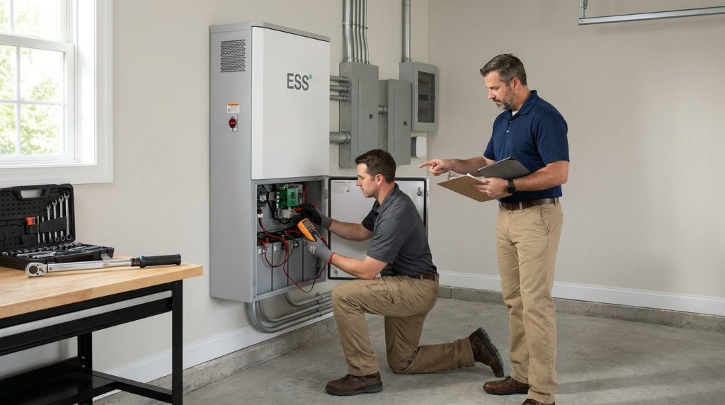
Before power-up, the cabinet should be treated as unproven equipment. The crew checks damage, labels, clearances, breaker positions, grounding, conductor torque, polarity, PV and grid wiring, battery condition, and communication cables before any energization.
The pre-power-up inspection should start with simple visible items, then move into electrical and communication checks. This includes shipping damage, cabinet anchoring, ventilation, emergency labels, working clearance, disconnect positions, grounding, bonding, cable routing, polarity, torque values, and the condition of battery and inverter terminals.
- Confirm the cabinet model, battery model, inverter model, and serial numbers match the project documents.
- Check that AC and DC disconnects, breakers, and emergency shutdown devices are in the correct starting position.
- Verify grounding, conductor routing, polarity, torque, PV input, grid input, backup output, meter wiring, and CT orientation.
- Inspect communication cables for the BMS, inverter, EMS, meter, and network connection.
- Confirm required permits, utility steps, or local inspection requirements before energization.
For compact installations, clearance and access are especially important. A small-space cabinet still needs service access, airflow, and a safe work area. See compact home ESS for related placement considerations.
How Do Installers Power Up the ESS Without Creating Faults?
Installers should power up an all-in-one ESS in the manufacturer-approved sequence. The exact order depends on the cabinet and inverter design, but the principle is the same: energize in controlled stages, confirm status at each stage, and do not move forward if a fault appears.
A typical sequence may involve checking all disconnects first, waking the battery or BMS, bringing the inverter online, confirming grid and PV inputs, and then testing backup or protected-load operation. The homeowner may observe the process, but internal breakers, disconnects, covers, and commissioning software should remain under qualified installer control.
- Confirm all starting positions.
- Power the system in the approved order.
- Watch status lights, inverter screens, and commissioning software.
- Pause if alarms, communication faults, abnormal sound, odor, or heat appear.
- Continue only after each stage shows normal status.
How Do You Confirm the BMS and Inverter Are Talking?
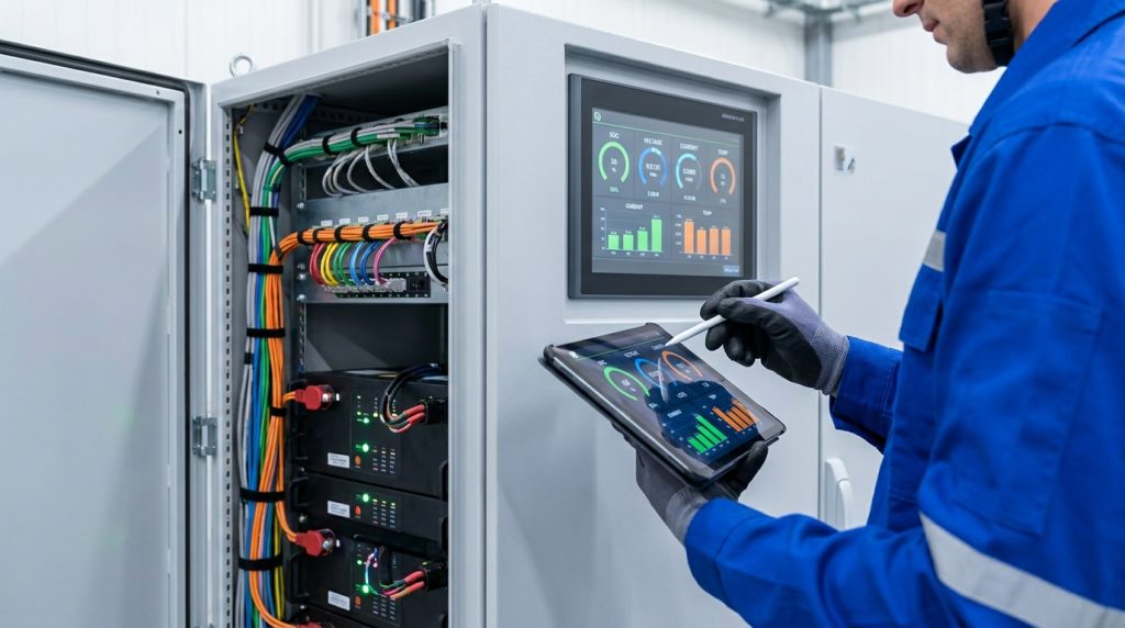
The BMS-inverter handshake is confirmed when the inverter sees the correct battery protocol and displays live battery data such as voltage, current, temperature, SOC, alarms, and model or serial information. If data is missing or wrong, stop and fix communication.
The BMS is not only a monitoring feature. It tells the inverter the battery’s safe charge and discharge limits, temperature condition, SOC, and alarm status. If the inverter cannot read this information correctly, the system should not be treated as ready for handoff.
What “Pass” Looks Like
- The inverter detects the correct lithium battery mode or battery protocol.
- SOC, voltage, current, and temperature values appear live and look reasonable.
- No active BMS communication alarm is shown.
- Charge and discharge limits are visible or correctly applied.
- The EMS or app shows the battery as online.
What Should Stop the Test
- No SOC, voltage, temperature, or current data appears.
- The inverter shows a BMS communication fault.
- The wrong battery protocol is selected.
- Battery data freezes or updates inconsistently.
- The installer cannot confirm CAN or RS485 communication.
A failed BMS handshake should stop the visit. It is safer to delay handoff than to bypass battery communication or leave the inverter operating without reliable live battery limits.
What Does EMS Provisioning Include on Day One?
EMS provisioning turns a powered system into a managed system. The installer enters site, utility, PV, meter, reserve SOC, operating mode, network, and user-access settings so the cabinet follows the job design and can be monitored.
This step connects the hardware to the real use case. The EMS may need the correct time, location, utility profile, PV configuration, meter assignment, CT direction, backup reserve, charge/discharge mode, and homeowner monitoring account. Without these settings, the system may power on but still behave incorrectly.
- Set the operating mode, such as backup priority, self-consumption, or solar-storage use.
- Confirm reserve SOC and outage behavior.
- Connect WiFi or Ethernet if the system requires remote monitoring.
- Verify meter and CT readings match the site’s real import and export direction.
- Prepare app access for the homeowner.
For solar-connected systems, EMS settings must match the PV and battery design. Readers who need broader context can review solar battery systems.
What Should the 14-Step All-in-One ESS Commissioning Checklist Include?
The checklist should move from paperwork and inspection to power-up, communication, testing, documentation, and training. This keeps the commissioning visit organized and helps the homeowner understand what “ready” actually means.
| Step | Who Confirms | What to Verify | Pass Evidence | Stop If |
|---|---|---|---|---|
| 1 | Site supervisor | Permits, AHJ steps, utility status, and emergency plan | Documents available | Required approval is missing |
| 2 | Installer | Cabinet, inverter, battery model, and serial numbers | Matches project documents | Equipment does not match design |
| 3 | Installer | Shipping damage, seals, labels, clearance, and ventilation | Visual inspection passed | Damage, blocked airflow, or missing labels appear |
| 4 | Installer | Cabinet anchoring and safe work area | Cabinet is stable and accessible | Cabinet is loose or access is unsafe |
| 5 | Installer | AC and DC breakers, disconnects, and E-stop position | Correct starting state | Unknown or unsafe breaker state |
| 6 | Installer | Grounding, bonding, conductor routing, torque, and polarity | Checked against documentation | Wrong polarity or loose connection is found |
| 7 | Installer | PV, grid, backup-load, meter, and CT wiring | Wiring matches plan | CT direction or wiring is uncertain |
| 8 | Installer | Battery SOC, temperature, and BMS readiness | BMS data available | Battery data is missing or abnormal |
| 9 | Installer | Staged power-up sequence | No fault during energization | Alarm, odor, heat, noise, or trip appears |
| 10 | Installer | BMS-inverter handshake | Live SOC, voltage, current, temperature, and no comm fault | BMS communication fails |
| 11 | Installer | EMS, network, time, utility, PV, reserve SOC, and mode | Settings saved and visible | Meter or operating mode is wrong |
| 12 | Installer | Charge and discharge commissioning tests | Results recorded | Test fails or readings are abnormal |
| 13 | Installer | Transfer-switch or backup simulation test | Protected loads operate as designed | Backup path fails or loads drop unexpectedly |
| 14 | Installer and homeowner | Homeowner app, alarms, support contact, warranty, and safe boundaries | Handoff complete | Homeowner cannot access monitoring or support details |
This checklist also shows why plug-and-play battery claims need context. An all-in-one cabinet can simplify installation, but it still needs verified wiring, communication, settings, backup behavior, and handoff.
How Should the Transfer-Switch or Backup Test Be Run?
A transfer or backup test proves the ESS can support protected loads during a simulated grid outage. The installer should follow the manufacturer sequence, confirm the backup path operates, restore grid power, and record pass or fault details.
This test should never be improvised. The installer should use the approved procedure for the cabinet, inverter, and transfer equipment. The goal is to confirm that the selected protected loads stay powered or transfer as designed, then return safely to normal grid-connected operation.
- Confirm which loads are connected to the backup or protected-load panel.
- Simulate grid-down only through the approved method.
- Check whether critical loads operate as expected.
- Restore grid power and confirm normal operation returns.
- Record the test result, fault codes, and any corrective action.
A homeowner can observe the backup demonstration, but the installer should control the test. The homeowner’s main takeaway should be what will stay powered, what will not, and what the app or display should show during an outage.
What Readings and Results Should Be Recorded Before Sign-Off?
A green screen is not final proof. App visibility is useful, but recorded charge/discharge results, BMS communication status, backup test results, and EMS settings give stronger evidence that the system was actually commissioned.
The site supervisor should make sure the installer records the key values, screenshots, fault status, and pass/fail notes before final handoff. This helps with warranty support, future troubleshooting, and homeowner confidence.
| Item | What to Record | Why It Matters |
|---|---|---|
| Battery status | SOC, voltage, current, temperature, and alarms | Confirms BMS data is visible and reasonable |
| Inverter status | Battery protocol, operating mode, grid status, and fault codes | Confirms inverter setup matches the system design |
| EMS settings | Mode, reserve SOC, utility, meter, CT direction, and network | Confirms the cabinet will operate according to the site plan |
| Charge test | Charge power, battery response, and alarms | Confirms the system can accept energy safely |
| Discharge test | Discharge power, load response, and battery limits | Confirms the system can supply energy safely |
| Backup test | Transfer result, protected loads, and restore result | Confirms outage behavior before handoff |
| Homeowner app | Login, device visibility, normal status, and support contact | Confirms the owner can monitor the system |
What Should the Homeowner Learn Before the Installer Leaves?
Homeowner training should cover daily monitoring, outage behavior, reserve SOC, alarm meanings, support contacts, and safe boundaries. It should not teach the homeowner to bypass protection, open the cabinet, or operate disconnects without qualified guidance.
The homeowner should know what normal operation looks like in the app, what the reserve SOC means, which loads are backed up, what happens status, and support contact Confirms the owner can monitor the system
- How to log in to the app and confirm normal system status.
- What SOC, backup reserve, charge, and discharge mean.
- What the system should do during a grid outage.
- Which alarms require a service call.
- What not to touch, including internal cabinet parts, breakers, and disconnects.
- Where warranty, support, and commissioning documents are stored.
For broader owner education, the writer can link to home energy storage basics without repeating full pillar content.
When Should Commissioning Stop Instead of Pushing Through?
Commissioning should stop when a safety, wiring, communication, or permission issue is unresolved. A failed test is useful information, not an invitation to bypass the BMS, ignore fault codes, or leave the homeowner with an unstable system.
The safest commissioning teams do not treat warnings as small inconveniences. They document the fault, identify the likely cause, correct it, and retest. This is especially important for BMS communication, grounding, polarity, abnormal heat, breaker trips, backup transfer failure, and missing inspection or utility steps.
| Symptom | Likely Issue | First Check | Stop or Continue? |
|---|---|---|---|
| No BMS data | Communication cable, protocol, or battery wake issue | CAN or RS485 wiring and battery protocol | Stop |
| Wrong SOC or frozen data | BMS communication or configuration issue | Battery status and inverter protocol | Stop |
| Hot lug during load test | Loose or incorrect termination | Torque and conductor condition | Stop |
| Breaker trip | Wiring, overload, or protection issue | Load, polarity, and breaker rating | Stop |
| Backup test fails | Transfer path, load panel, or settings issue | Backup wiring and operating mode | Stop |
| App offline | Network or provisioning issue | WiFi, Ethernet, account, and EMS status | Continue only if local commissioning data is verified |
| CT direction error | Meter or CT orientation issue | CT arrow direction and meter assignment | Stop before final EMS sign-off |
Plug-and-play is not no-commissioning. A cabinet can be neatly installed and still fail a communication, backup, or EMS test. The better decision is to pause, document the issue, and leave only after the system passes the required checks.
FAQ
What is the single most important test during commissioning?
The most important test is confirming polarity and conductor termination before energization. Reversed cables or loose lugs can damage equipment and create heat, while failed BMS communication can prevent the inverter from following safe battery limits.
Can I use a cheap multimeter for my cabin ESS?
A basic multimeter can help with simple voltage and continuity checks, but it is not enough for professional all-in-one ESS commissioning. The installer should use properly rated meters, torque tools, manufacturer software or app access, and any test equipment required by the manual.
How do I know what the correct torque for electrical connections is?
The correct torque comes from the cabinet, inverter, battery, breaker, or lug manufacturer documentation. Do not estimate it, because over-tightening can damage hardware while under-tightening can increase resistance and heat at high-current connections.
Do I need permits to install a home storage system?
In many regions, yes. ESS installations often need to meet local electrical, fire, utility interconnection, and inspection requirements. The installer should confirm AHJ and utility steps before commissioning day, not after the cabinet is powered.
How do I know the BMS and inverter are communicating?
The inverter or commissioning screen should show live battery data, the selected lithium battery protocol, and no active communication fault. At minimum, the installer should confirm SOC, voltage, current, temperatures, alarms, and charge/discharge limits are visible and reasonable.
What should the homeowner do during commissioning?
The homeowner should watch the app setup, outage demonstration, and final operating-mode explanation, but should not touch breakers, disconnects, or cabinet hardware. Their role is to learn normal status, alarm meanings, support contacts, and when to call the installer.
What happens if the commissioning test fails?
A failed commissioning test should pause the handoff. The installer should record the error, identify whether it is wiring, communication, settings, meter, firmware, or utility-related, then correct and retest before marking the system complete.

-

 OEM Residential Energy Storage Solutions: Passive vs. Active Cell Balancing
2026-09-30
-
 Smart Home Battery with BMS Communication: Cybersecurity and BMS Safety
 -
 10kWh Home Battery Backup System: Is 90% DoD Better for Daily Solar Storage?
2026-09-29
-
 Integrated Home Energy Storage System 150–430V MPPT Design
2026-09-28
-
 LiFePO₄ Residential Backup Battery SOC Accuracy in Parallel Systems
Share this:





.svg)






-899.svg)


