




Parallel Battery Storage: Safe Wiring & BMS Sync
A parallel battery storage system adds capacity at the same voltage, but it is only safe when each module has equal-length conductors, correct branch protection, rated busbars, and approved BMS communication. Use a busbar layout for 2 or 3 modules, confirm SOC and firmware first, then verify current sharing during the first charge and discharge.
Parallel battery wiring looks simple from the outside: positive to positive, negative to negative. In a home energy storage install, that shortcut is not enough. A 2 or 3-module bank needs balanced cable paths, correctly rated hardware, branch protection, and a BMS network that accepts every module before the inverter starts. This guide shows what to check before power-up, during commissioning, and when one module behaves differently from the others.
What changes when battery modules are wired in parallel?
In a parallel battery storage system, module voltage stays the same while total capacity increases. Two 5 kWh modules become roughly 10 kWh at the same voltage, but usable current still depends on BMS limits, cable sizing, and protection.
Parallel wiring increases stored energy without changing the battery bank’s nominal voltage. If one 48 V-class module stores 5 kWh, two matching modules in parallel create about 10 kWh. Three matching 5.12 kWh rack modules create about 15.36 kWh of nominal storage.
That extra capacity does not mean the installer can ignore current limits. The battery modules, Battery Management System (BMS), busbars, fuses, conductors, and inverter all set the safe operating range. The U.S. Department of Energy describes battery energy storage systems as a group of cells, modules, management systems, and protection devices working together, not as batteries alone. backup runtime math becomes the next step once the parallel bank is safely built.
Can your 2 or 3 modules be paralleled safely?
Only parallel battery modules that the manufacturer approves for parallel operation. Match voltage, chemistry, capacity class, firmware, SOC, and BMS communication rules before connecting, because mismatched modules can create circulating current, alarms, heat, or premature aging.
A safe parallel bank starts before the cable is installed. The installer should confirm that the modules are the same model or listed as compatible by the manufacturer. They should also confirm nominal voltage, chemistry, allowed parallel count, firmware version, and BMS communication method.
- Same nominal system voltage
- Same chemistry, such as LiFePO4
- Same model or approved mixed-module setup
- Similar State of Charge (SOC)
- Supported BMS protocol and module addressing
- No damaged case, terminal, fuse holder, or communication port
- Manual confirms the planned 2 or 3-module parallel count
Mismatched batteries can create circulating current, which means current moves between modules instead of only serving the load. That can cause heat, SOC drift, alarms, or shortened service life. If the plan is to add more kWh, the expansion should follow the battery manual first, then the inverter manual.
What is the safest busbar layout for a parallel battery storage system?
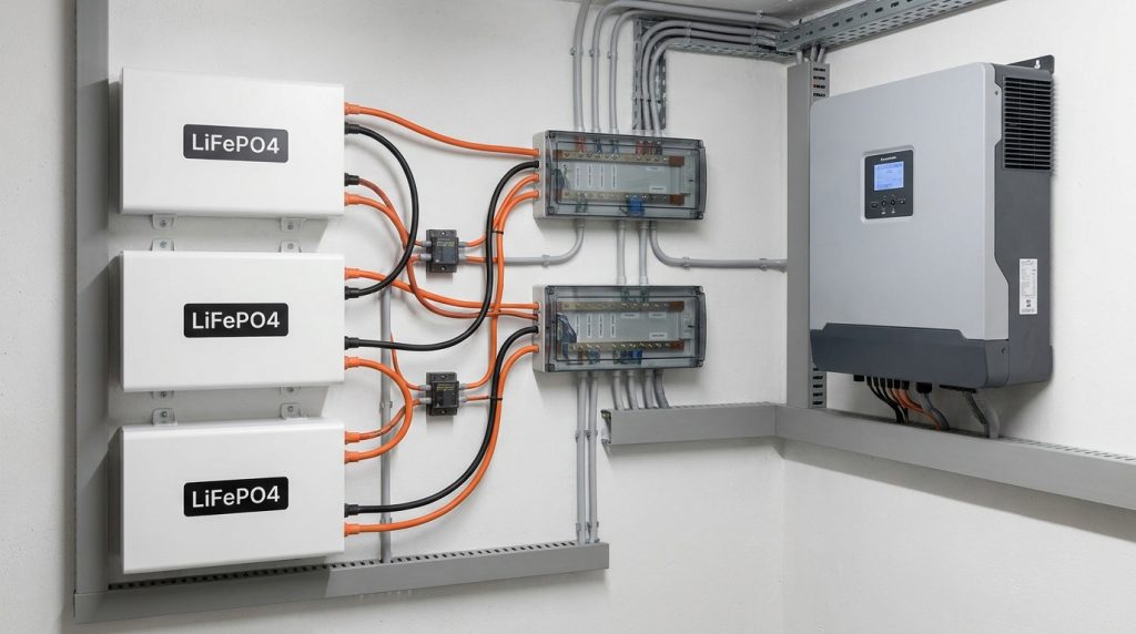
A busbar-centered layout is usually safer than a jumper chain for 2 or 3 home ESS modules because it gives each module a similar electrical path, makes fuse placement clearer, and makes current-sharing problems easier to inspect.
A jumper chain is not automatically wrong. It works when the manufacturer supplies a dedicated parallel kit and the manual approves the exact layout. For larger home ESS modules, a busbar layout is usually cleaner because each module has its own branch path into a shared positive and negative point.
The safest layout uses one positive busbar and one negative busbar. Each module’s positive lead should pass through its own branch fuse or breaker before it lands on the positive busbar. Each negative lead should land on the negative busbar with the same length and cable gauge as the other modules.
Labeled 3-module busbar layout
| Label | Connection | What to check |
|---|---|---|
| Battery Module 1 | Positive lead to branch fuse, then positive busbar | Same cable length and gauge as Modules 2 and 3 |
| Battery Module 2 | Positive lead to branch fuse, then positive busbar | Same fuse type and current rating |
| Battery Module 3 | Positive lead to branch fuse, then positive busbar | Same routing and bend radius |
| Module negatives | Each negative lead to negative busbar | Equal-length negative conductors |
| Positive busbar | Main positive lead to DC breaker, then inverter | Busbar rated for total bank current |
| Negative busbar | Main negative lead to inverter negative input | Tight lug torque and clean contact surface |
| BMS communication | Master/slave, CAN, RS485, or hub path | Correct address, order, and termination |
Victron’s parallel BMS documentation also points to equal-length load-side busbar cables for balanced current sharing. That same idea applies to home module layouts: keep each module’s electrical path as equal as practical. For broader design planning, this ties directly into modular battery design.
How should busbars, cables, fuses, and disconnects be sized?
Size each branch cable and fuse for the module’s allowed current, then size the busbars, main conductors, and main disconnect for the total parallel bank current. Never size shared hardware as if only one module can supply current.
A parallel bank has two current zones. Branch hardware serves one module. Shared hardware serves the combined bank. If three modules can each supply current, the main busbar and main conductors must be rated for the combined safe output allowed by the battery and inverter manuals.
NFPA keeps safety resources for stationary energy storage systems, and NFPA 855 covers installation safety requirements for stationary ESS equipment. The article should not replace local code or the product manual. It should help the reader know which hardware needs careful confirmation.
| Hardware | Current path | Sizing logic |
|---|---|---|
| Module branch cable | One battery module | Match module current, cable length, temperature, and manual limits |
| Branch fuse or breaker | One module positive lead | Protect that module branch before it reaches the busbar |
| Positive busbar | Combined battery output | Rate for total approved bank current |
| Negative busbar | Combined return current | Rate the same as the positive side |
| Main DC breaker | Full bank output | Isolate the entire bank from the inverter |
| Main inverter leads | Total bank current | Match inverter, bank, cable length, and code requirements |
Do not rely on a single “battery cable size” answer from the internet. A short rack cable, wall-mounted cable run, warm enclosure, and high-current inverter can all change the safe choice.
How does master/slave BMS sync work before the inverter starts?
BMS sync lets parallel modules behave like one controlled battery bank. The system checks voltage, SOC, alarms, and communication before contactors close, then reports combined limits only for modules that are online and accepted by the BMS network.
The BMS is the control layer that watches voltage, current, temperature, SOC, and fault status. The Department of Energy describes BMS functions as part of battery energy storage safety and control. In a parallel bank, that control layer must see the modules before the inverter treats them as one battery.
Some systems use one master module and one or more slave modules. Others use a hub or virtual battery bank. Victron’s documentation describes a parallel BMS setup where active BMS units combine their current limits, and a voltage difference can keep a unit in a pending state before contactors close.
What the BMS should confirm before closing contactors
- Each module is powered and awake.
- Module voltage and SOC are within the allowed range.
- No module is reporting a critical alarm.
- Communication order, address, and termination are correct.
- Charge and discharge current limits are accepted.
- The inverter sees the correct battery protocol.
Here is a practical case. A new module is added at a higher SOC than the existing bank. The BMS may delay contactor closure until the voltage difference is safe. That delay is not a wiring failure by itself. It becomes a problem if the system never accepts the module, reports reduced capacity, or shows communication loss. For closed control designs, all-in-one ESS controls may handle more of this logic inside one cabinet.
Why do unequal cables cause poor current sharing?
Unequal cables cause poor current sharing because each module sees a different resistance path to the busbar. The lower-resistance path carries more current, so that module heats more, cycles harder, reaches limits sooner, and may trigger BMS alarms.
Current follows the easier path. In a parallel bank, a shorter lead, thicker cable, cleaner lug, or tighter terminal can make one module carry more of the load. The difference may look small during light use, then become clear during inverter startup, heavy discharge, or strong charging.
Do not rely on the BMS to fix bad wiring. A BMS can protect and disconnect, but it cannot make unequal cable resistance disappear. The physical layout still has to give each module a fair path to the busbars.
| Failure mode | What it looks like | Likely cause | First check |
|---|---|---|---|
| One module discharges faster | SOC drops sooner than others | Lower resistance path or older module | Cable length, gauge, and module health |
| One module runs warmer | Terminal or case temperature rises | Loose lug or high current load | Torque, lug surface, branch current |
| Repeated BMS alarms | Module hits current or voltage limit first | Unequal sharing or SOC mismatch | Current readings and SOC alignment |
| Circulating current | Modules exchange current at rest | Voltage or SOC mismatch | Pre-connect voltage and SOC |
| Fuse trips on one branch | One path overloaded | Wrong fuse, cable issue, or module fault | Fuse rating and branch current |
A simple example helps. Module A has a shorter positive lead than Module C. Under load, Module A may carry more current, reach its discharge limit sooner, and trigger an alarm before the other modules are working evenly.
What commissioning sequence should the installer follow?
The installer should commission a parallel bank in a controlled order: inspect first, connect with all loads off, confirm BMS communication, then test current sharing during the first charge and discharge. Skipping this order can hide wiring errors until the bank is under real load.
- Confirm each module model, voltage, chemistry, and allowed parallel count.
- Bring module SOC close together before final connection.
- Turn off inverter, PV input, charger, and household loads tied to the system.
- Verify polarity on every cable before landing it.
- Install branch fuses or breakers on each positive module lead.
- Land equal-length module leads on positive and negative busbars.
- Torque terminals to the manufacturer’s value.
- Connect BMS communication cables in the approved order.
- Set module addresses or DIP switches if required.
- Power the BMS network and confirm every module is visible.
- Close the main battery disconnect only after BMS status is normal.
- Start the inverter and check battery recognition.
- Run a light charge and discharge test.
- Compare module current, SOC drift, and temperature.
- Increase load only after current sharing looks normal.
For solar-connected systems, the battery bank should not be treated as a separate island from the inverter and PV design. The commissioning order should also match the hybrid solar battery setup approved for the site.
How do you troubleshoot imbalance, alarms, or one module carrying more current?
If one parallel module carries noticeably more current, do not assume the BMS will fix it. Check cable length, cable gauge, lug torque, branch fuse condition, SOC alignment, and BMS communication before running higher loads.
A parallel bank should not show one module doing most of the work under the same conditions. Small differences can happen, but repeated large gaps point to wiring, SOC, communication, or module health issues. Stop high-load testing until the installer checks the cause.
| Symptom | Likely cause | What to check first | Stop and call installer? |
|---|---|---|---|
| One module current is much higher | Unequal cable resistance | Cable length, gauge, and busbar landing | Yes, before heavy load |
| One module stays offline | BMS address, breaker, or contactor issue | Address setting, branch breaker, communication cable | Yes |
| SOC drifts after each cycle | Initial SOC mismatch or weak module | SOC alignment and module health data | Yes, if drift repeats |
| Hot terminal or cable end | Loose lug or high resistance joint | Torque, lug surface, discoloration | Yes, immediately |
| Inverter reports reduced capacity | One module not accepted by BMS | CAN/RS485 order, firmware, battery protocol | Yes |
| Branch fuse trips | Overcurrent or wrong fuse rating | Branch current and fuse specification | Yes |
| Battery alarm during startup | Voltage difference or communication fault | Pre-connect voltage and BMS status | Yes |
Here is a common service case. The inverter reports less capacity than expected after a third module is added. The installer should not just clear the alarm. They should confirm the third module is online, accepted by the BMS network, addressed correctly, and included in the inverter’s reported battery limits.
When should you avoid paralleling battery modules?
Avoid paralleling modules when the manufacturer does not approve the combination, the wiring cannot be protected correctly, or the installer cannot verify current sharing after startup. A parallel bank that looks neat can still be unsafe if the modules or control system do not match.
- Different battery chemistry
- Different nominal voltage
- Damaged terminal, case, fuse holder, or communication port
- Unknown SOC difference between modules
- Unsupported old and new module mix
- Firmware mismatch that blocks BMS communication
- Manual forbids the planned parallel count
- No branch fuse or breaker on each module positive lead
- Shared busbar or main conductor is underrated
- Installer cannot read module-level current or status
Adding a third module is not simply adding more energy storage. It changes fault current, main conductor sizing, busbar rating, BMS reporting, and commissioning checks. If the current setup cannot support safe expansion, step back and plan the bank as part of scalable ESS planning.
What should you check next in the full home ESS design?
After the parallel wiring is safe, check whether the full system still fits the home’s backup goal. That means load priority, inverter rating, solar charging behavior, transfer setup, and future expansion path. Use the home energy storage system guide for broader system planning, then return to this article when reviewing the battery bank layout with your installer.
Getting the Next Step Right
A safe parallel battery storage system depends on small details that are easy to miss during a fast install. Equal-length conductors, branch protection, rated busbars, clean torque, and BMS sync all affect how the bank behaves under real load. Ask the installer to show the busbar layout, confirm module-level current readings, and document the startup checks before the system becomes your main backup power source.
Frequently Asked Questions
What happens when batteries are connected in parallel?
Batteries connected in parallel keep the same system voltage while total capacity increases. For example, two equal 5 kWh modules create about 10 kWh of nominal storage, but safe output still depends on BMS limits, wiring, fuses, and inverter compatibility.
Can I mix different battery types or capacities in parallel?
You should not mix different battery chemistries, unsupported capacities, old and new modules, or different BMS platforms in parallel. Even if the voltage looks similar, mismatch can cause circulating current, uneven charging, BMS alarms, heat, and warranty problems.
Can I use regular wire instead of a busbar?
For a small approved bank, manufacturer-supplied parallel cables may be acceptable, but a busbar layout is usually cleaner for 2 or 3 modules. Busbars make equal cable length, branch fusing, inspection, and future service easier.
Why are my parallel batteries unbalanced?
Parallel batteries usually become unbalanced because the modules are mismatched, initial SOC is different, cable lengths are unequal, terminal torque is inconsistent, or BMS communication is not working. The installer should verify current readings module by module before increasing load.
What cable size should be used for parallel batteries?
Cable size depends on the module current rating, total bank current, cable length, installation temperature, and local code. Use the battery and inverter manuals first, then confirm that branch cables, busbars, and main conductors are all rated for their actual current path.
What happens if one battery fails in a parallel battery bank?
If one module fails, a well-designed BMS may disconnect that module while the remaining modules continue at reduced capacity and current. The bank should still be inspected because the fault may come from wiring, SOC mismatch, heat, or communication loss.
What happens if there is a communication loss between BMSes?
BMS communication loss can make the system derate, split into standalone operation, lose virtual-bank reporting, or stop charging coordination. The exact behavior depends on the manufacturer, so installers should verify communication order, addresses, firmware, and inverter battery protocol.

-

 OEM ODM Home Energy Storage Manufacturer for Stackable Home Battery Solutions
2026-08-20
-
 High-Rate Discharge in Data Center UPS Battery Backup Systems Explained
 -
 LiFePO₄ RV Battery 48V System Design: Battery, Inverter, Solar and DC Load Integration
2026-08-19
-
 51.2V LiFePO₄ Server Rack Batteries: 100Ah Capacity, Energy Output and Runtime
2026-08-18
-
 51.2V 100Ah LiFePO₄ Battery for Inverter in Solar Energy Storage Systems
2026-08-17
Share this:






.svg)






-899.svg)


