




Commercial Battery Storage Sizing: kW, kWh, Runtime and Load Profile
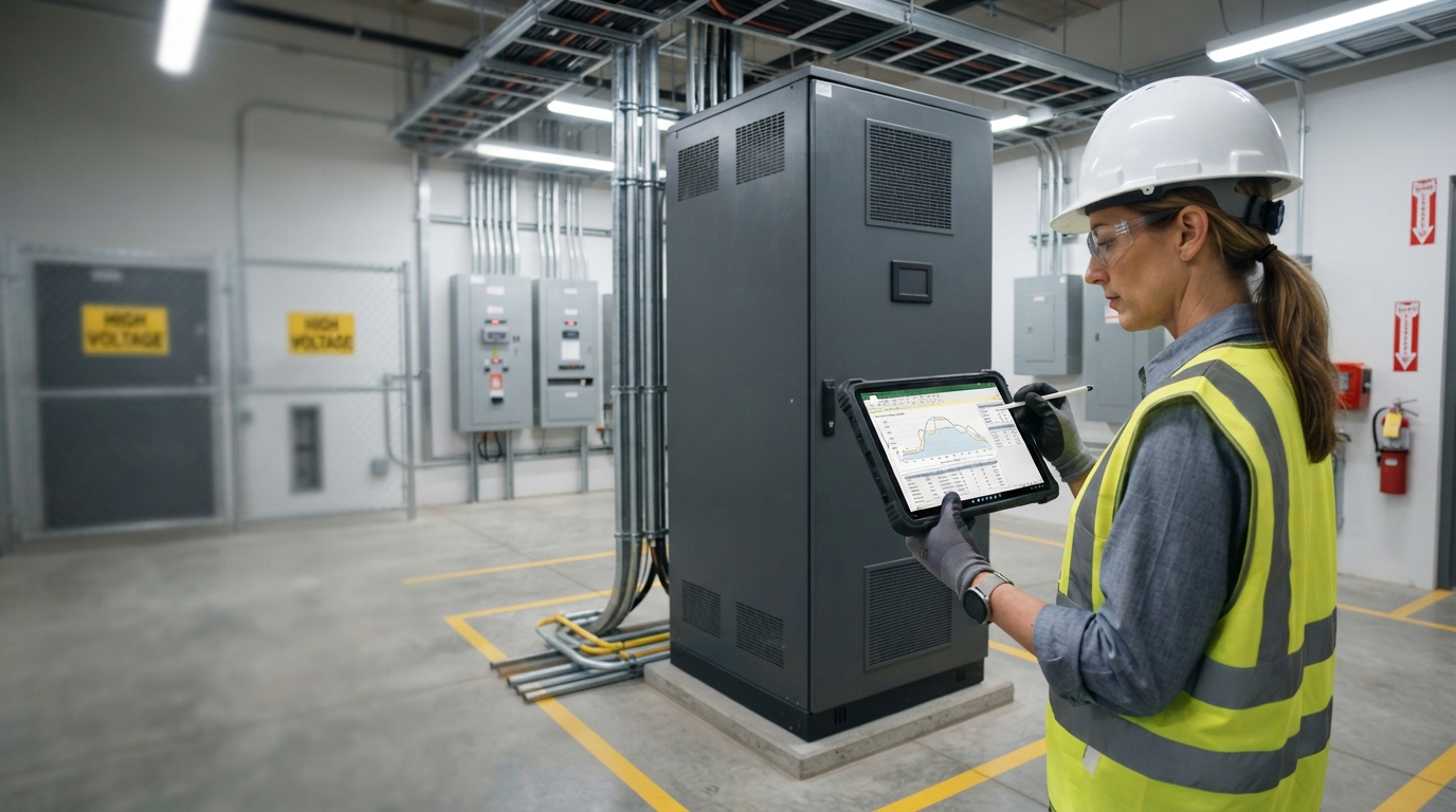
Commercial battery storage sizing is the process of turning a facility’s demand pattern into three practical numbers: the battery’s power output in kW, its energy capacity in kWh, and the runtime it can provide. The right values depend heavily on the application—peak shaving, backup power, solar self-consumption, or load shifting—so sizing always starts with the site’s load profile and operating objective.
This page works like a manual sizing worksheet. Follow the steps, insert your own numbers, and you should end with a preliminary size you can use for budgeting, supplier discussions, or a more detailed engineering review.
kW, kWh, and Runtime: The Three Sizing Outputs
A commercial battery specification is incomplete without both a power rating and an energy rating.
| Term | Unit | What it tells you |
|---|---|---|
| Power | kW | How much load the battery can support at a single moment |
| Energy | kWh | How much total work the battery can deliver over time |
| Storage duration | hours | The relationship between energy and power, usually kWh ÷ kW |
| Runtime | hours | How long the stored energy can supply a specific load |
A system rated 100 kW / 200 kWh can deliver 100 kW for about two hours at rated output. If the load drops to 50 kW, the same battery could run for roughly four hours, because the usable energy is divided by a smaller load.
Runtime is therefore an estimate, not a fixed datasheet value. It depends on the actual load, the battery’s usable energy, and the system’s operating limits.
The U.S. Department of Energy’s BESS evaluation method makes the same distinction clear: power describes the rate of energy delivery, while capacity describes the amount of energy stored. Commercial battery storage data from the National Renewable Energy Laboratory also describes systems by both power and duration, not by power alone.
The Core Sizing Formula
The basic logic fits into four simple equations:
- Usable energy (kWh) = Load (kW) × Duration (hours)
- Required power (kW) = Peak demand (kW) − Target demand (kW), or = Critical load (kW) + starting allowance
- Nominal energy (kWh) = Usable energy (kWh) ÷ (Depth of discharge × Round-trip efficiency)
- Runtime (hours) = Usable energy (kWh) ÷ Average load (kW)
Depth of discharge and round-trip efficiency should be used as decimals. For example, an 80% DoD is 0.8, and a 90% round-trip efficiency is 0.9.
The third equation is the one that catches most buyers off guard. Battery datasheets usually state nominal energy, but the load only receives usable energy after the system’s operating limits and efficiency losses are applied.
Step 1: Define the Sizing Objective
The same facility can need two completely different battery sizes depending on the goal.
| Objective | Main driver | Dominant output |
|---|---|---|
| Peak shaving | Peak demand minus target demand | Power in kW, then energy from event duration |
| Backup power | Critical load and required outage runtime | Both kW and kWh |
| Solar self-consumption | Excess PV generation or evening load | Energy in kWh; power set by inverter/EMS design |
| Load shifting | Load moved to a cheaper or lower-demand period | Energy in kWh; power set by the load rate |
For peak shaving, calculate how much demand must be clipped and for how long.
For backup power, list the loads that must remain online, their starting characteristics, and the required runtime. The result is often a smaller power number but a much larger energy number than peak shaving alone would suggest.
For solar self-consumption, the battery stores surplus PV output and discharges when the building needs it. Sizing depends on the net load, not just the gross facility load.
If the site needs more than one service, the safest approach is to calculate the largest power requirement and the largest energy requirement separately, then check whether one system can satisfy both. More on that in the comparison section below.
Step 2: Analyze the Commercial Load Profile
The load profile is the foundation of every sizing calculation.
The most useful data is 15- or 30-minute interval data from the utility meter. Twelve months of data gives the clearest picture, but a representative month that includes the facility’s peak season is a reasonable starting point.
Look specifically for:
- Peak demand — the highest kW value, and when it occurs.
- Demand interval — whether the utility charges on a 15-minute, 30-minute, or 60-minute interval.
- Event duration — how long the peak or critical period lasts.
- Critical loads — which equipment must continue running in an outage.
- Starting currents — motors, compressors, elevators, and other loads that draw more current at startup.
- Baseload — the overnight and weekend load that affects recharge opportunities.
- Solar net load — facility load minus PV generation, if solar is already installed.
National Renewable Energy Laboratory research on demand-charge mitigation shows that storage sizing for demand reduction depends heavily on the shape of the load profile, not just the monthly peak. A flat profile needs a different system than a profile with one sharp afternoon spike.
Step 3: Calculate the Power Requirement in kW
Once the load profile is understood, the power calculation is straightforward.
- For peak shaving:
Required kW = Peak demand − Target demand If the facility peaks at 500 kW and the target is 400 kW, the battery and PCS must be able to deliver at least 100 kW.
- For backup power:
Required kW = Critical load + starting allowance The steady-state critical load may be 80 kW, but a motor that draws 30 kW during startup can push the instantaneous requirement higher.
- For solar self-consumption or load shifting:
Required kW is usually the size of the load to be served, or the import limit the system is meant to enforce.
The result is the AC power the system must deliver. That means the PCS or inverter rating must be at least this value.
Power is not the same as capacity. A battery can have plenty of kWh but still fail to start or sustain a high-power load if the PCS, cabling, and battery C-rate are not rated for the required kW.
Step 4: Calculate the Energy Requirement in kWh
The energy calculation starts with the same load profile, then adjusts for real operating limits.
| Scenario | Usable energy requirement |
|---|---|
| Peak shaving | Required power (kW) × event duration (hours) × expected events per day |
| Backup power | Critical load (kW) × required runtime (hours) |
| Solar self-consumption | Excess PV energy or evening load (kWh) |
| Load shifting | Load shifted (kW) × shift window (hours) |
From there, convert usable energy into nominal energy:
Nominal kWh = Usable kWh ÷ (Depth of discharge × Round-trip efficiency)
Assume the building needs 200 kWh of usable energy, the battery can be discharged to 80%, and the round-trip efficiency is 90%:
200 ÷ (0.8 × 0.9) = 278 kWh nominal
In other words, specify a system with roughly 278 kWh of rated energy if the usable requirement is 200 kWh.
Some designers also add a degradation and load-growth reserve of 10–20% to keep the system useful in later years. That is a project decision, and it should be stated clearly as an assumption. World Bank battery storage procurement guidance makes the same point: rated capacity, usable capacity, operating limits, and degradation assumptions all need to be separated during project planning.
Step 5: Check PCS Power, Recharge Time, and Safety Limits
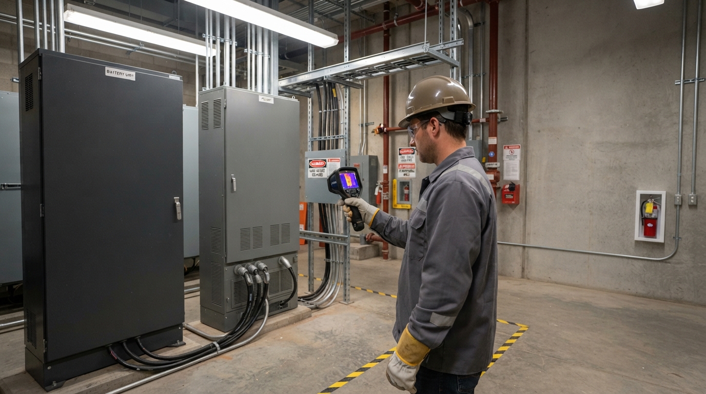
A preliminary size is not complete until it passes four checks.
1. PCS / inverter rating
The PCS must be able to deliver at least the required AC power from Step 3. If the battery has ample kWh but the PCS is rated too low, the system cannot serve the peak load.
This is also where system-level design begins. For containerised and higher-power projects, the interaction between battery capacity and PCS rating is critical; the bess container pcs sizing guide covers that decision in more depth.
2. C-rate
C-rate links power output to battery capacity:
C-rate = Required power (kW) ÷ Battery energy (kWh)
A 100 kW load on a 278 kWh battery is roughly a 0.36C discharge. That is generally moderate. A 100 kW load on a 100 kWh battery would be 1C, which places more stress on the cells and may shorten cycle life.
If the C-rate looks high, the practical fix is usually a larger-capacity battery, not a larger PCS alone.
3. Recharge window
A battery that discharges for a full peak event needs enough time and charge power to recover before the next event.
Check the building’s overnight and midday windows. If the system uses 200 kWh and has a 10-hour recharge window, the average recharge power is roughly 20 kW before losses. That usually requires a site-specific charge-power setting in the EMS.
4. Thermal and safety review
High-power cycling creates heat, so thermal management should be considered as part of the system design, not as an afterthought. Enclosure type, ambient temperature, and cooling method all affect sustained performance.
Fire-safety planning is equally important. Pacific Northwest National Laboratory community BESS safety guidance notes that stationary storage installations require planning for detection, suppression, ventilation, and emergency response. The specifics depend on local codes and the exact system configuration.
Sizing for Peak Shaving vs. Backup Power: A Quick Comparison
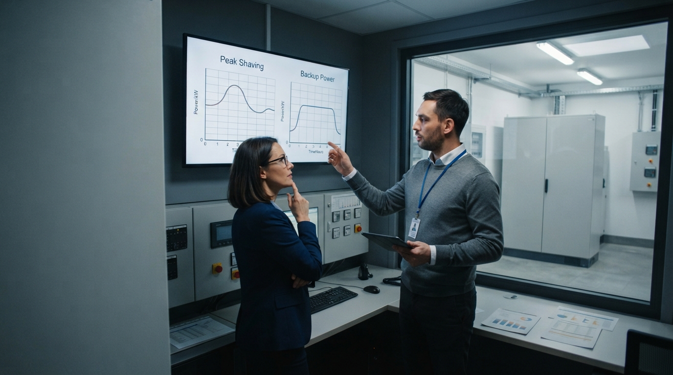
Many commercial projects start with one objective, then add the other later. The sizing logic is different.
| Factor | Peak shaving | Backup power |
|---|---|---|
| Goal | Reduce billed demand | Keep critical loads running |
| Main input | Peak demand and target demand | Critical load list and outage duration |
| Power calculation | Peak − target | Critical load + starting allowance |
| Energy calculation | Power × event duration × event count | Critical load × required runtime |
| Duration driver | Tariff interval and peak event length | Outage length and safety factor |
| Recharge driver | Time before the next peak event | Grid restoration time |
For a combined system, take the larger power result and the larger energy result, then recheck the PCS, C-rate, and recharge window.
Backup energy often dominates because an outage can last several hours, while a daily peak event might last only one or two hours. That is common, and it is exactly why the sizing objective must be defined before a supplier can give a meaningful recommendation. For projects focused specifically on resilience, the commercial backup energy storage solutions page covers that application in more depth.
Worked Example: Sizing a Commercial Battery for a 500 kW Facility
This example uses hypothetical numbers to show the full worksheet.
Inputs:
- Facility peak demand: 500 kW
- Target demand: 400 kW
- Peak event: 2 hours
- Critical load for backup: 80 kW
- Required backup runtime: 8 hours
- Depth of discharge: 80%
- Round-trip efficiency: 90%
Step A — Power for peak shaving:
500 kW − 400 kW = 100 kW
The system needs at least 100 kW of AC power from the PCS.
Step B — Usable energy for peak shaving:
100 kW × 2 hours = 200 kWh usable
Step C — Nominal energy for peak shaving:
200 ÷ (0.8 × 0.9) = 278 kWh nominal
So peak shaving alone points toward roughly a 100 kW / 278 kWh system.
Step D — Backup energy:
80 kW × 8 hours = 640 kWh usable
Step E — Nominal energy for backup:
640 ÷ (0.8 × 0.9) = 889 kWh nominal
If the facility needs backup as well as peak shaving, the backup energy requirement dominates. The power requirement is still 100 kW, but the battery energy jumps to roughly 889 kWh before any degradation reserve.
Step F — Quick validation:
- C-rate at 100 kW and 889 kWh: 100 ÷ 889 ≈ 0.11C, which is mild.
- Recharge over a 10-hour window: about 89 kW average charge power before losses.
- The EMS must confirm the charge window and dispatch logic.
This is an illustrative estimate, not a VoltaLink product recommendation. It shows why the objective and the load profile must be known before anyone can size a commercial battery properly.
If the facility later moves toward a larger power architecture, a 1mw battery storage container is a different scale and should be evaluated separately.
Common Commercial Battery Sizing Mistakes
Avoid these errors during the preliminary calculation:
- Sizing from average load instead of peak or critical load. Average load hides the real power requirement.
- Using nominal energy as though it were usable energy. The load never receives the full rated kWh after DoD and efficiency limits.
- Confusing Ah with kWh. Amp-hours only make sense when combined with system voltage. A 100 Ah battery at 48 V stores 4.8 kWh; at 400 V it stores 40 kWh.
- Forgetting the PCS/inverter limit. The battery may have enough energy, but the power path must also be large enough.
- Ignoring the recharge window. If the battery cannot recharge before the next event, it will not perform the next day.
- Omitting motor-start and inrush currents. Steady-state load calculations understate the momentary load.
- Skipping degradation and future load growth. A system sized exactly for today can be undersized within a few years.
- Treating the estimate as an engineering design. The calculation on this page is the starting point, not the final specification.
From a Preliminary Estimate to a Validated BESS Design
The worksheet above gives you a preliminary size. A real project needs engineering validation.
Before requesting pricing or selecting equipment, assemble the following:
- 12 months of interval load data, if available;
- the utility rate structure and demand interval;
- the target demand or critical-load list;
- the required runtime and number of discharge events per day;
- existing solar production data, if the system will be PV-coupled;
- site constraints, including available space, enclosure type, and environmental conditions;
- local electrical, fire-safety, and interconnection requirements.
Use those same inputs when speaking with suppliers. A well-prepared buyer should ask how the supplier defines rated energy, usable energy, PCS power, communication protocols, thermal management, enclosure rating, warranty conditions, and future expansion limits.
For commercial and industrial projects, the next step is to move from preliminary sizing to a system-level discussion. The ci energy storage system page is a practical place to start when you want to compare cabinet and container configurations against your preliminary numbers.

-

 OEM Residential Energy Storage Solutions: Passive vs. Active Cell Balancing
2026-09-30
-
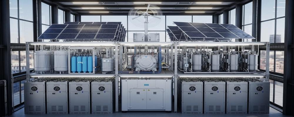 Smart Home Battery with BMS Communication: Cybersecurity and BMS Safety
 -
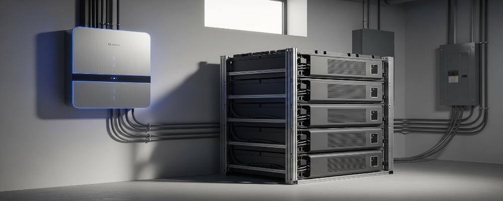 10kWh Home Battery Backup System: Is 90% DoD Better for Daily Solar Storage?
2026-09-29
-
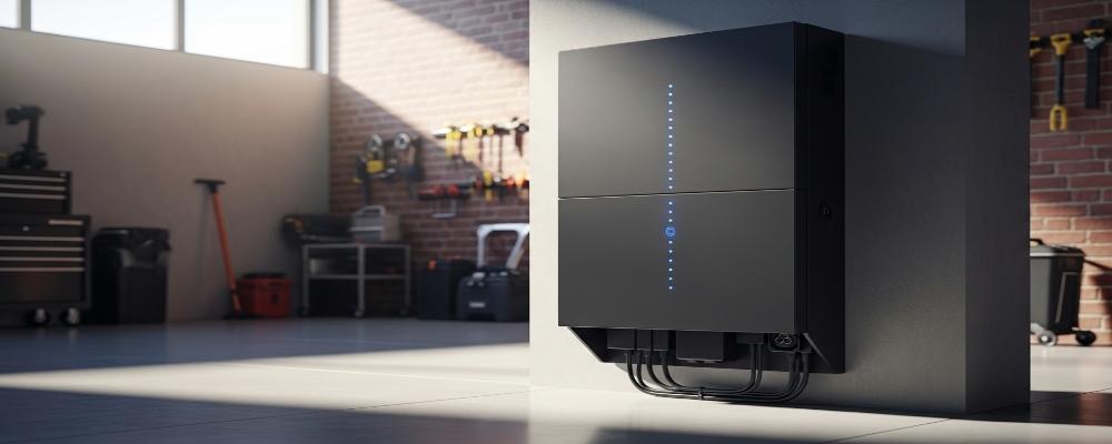 Integrated Home Energy Storage System 150–430V MPPT Design
2026-09-28
-
 LiFePO₄ Residential Backup Battery SOC Accuracy in Parallel Systems
Share this:






.svg)






-899.svg)


