




Integrated BMS Units: Pre-Wired Safety in One Box
Battery Management System integrated units are safer for most home ESS projects because the cells, sensors, protection logic, wiring, firmware, and inverter communication are built as one tested module. Compared with field-wired battery banks, they reduce wiring errors, simplify warranty evidence, and make CAN or RS485 faults easier to diagnose. They still require approved inverter matching, correct commissioning, and proper installation.
For installers and homeowners, the real question is not only “Does this battery have a BMS?” The better question is, “How much of the safety system was already engineered before it reached the site?” A pre-wired module can remove many hidden decisions from the installation process. That matters when the battery must protect itself, talk to the inverter, and support a clear warranty path.
What is an integrated BMS unit in a home battery system?
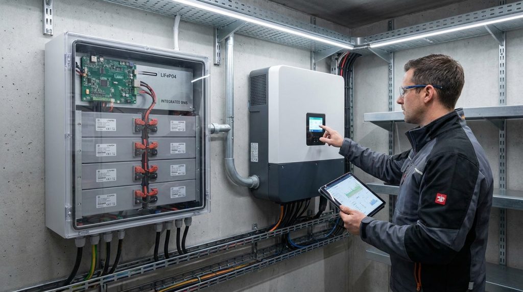
An integrated BMS unit is a battery module where the cells, protection electronics, sensors, wiring, firmware, and communication interface are engineered together. For home ESS buyers, it reduces field wiring decisions and makes safety behavior easier to verify.
In a home energy storage system, the Battery Management System is the control layer that watches the battery pack and keeps it inside safe limits. It monitors cell voltage, current, temperature, charge level, health, and fault conditions. A broader home energy storage guide can explain whole-system planning, but this article focuses on the BMS module itself.
The main difference is packaging and responsibility. With integrated units, the battery cells, balance wiring, sensors, protection logic, and communication port are built into one battery module. With a field-wired bank, many of those parts are selected, wired, configured, and tested on site.
For homeowners, that difference is simple. A pre-built module is easier to trust because fewer safety-critical choices happen during installation. For installers, it means less time spent proving that loose cells, a separate BMS board, and inverter settings all behave correctly together. You can still compare wider battery pack options when choosing the best format for the project.
Infineon describes integrated BMS designs as systems built directly into battery packs or modules. That is the core idea here: the BMS is not an add-on afterthought. It is part of the battery’s safety design.
Why is a pre-wired BMS safer than a field-wired battery bank?
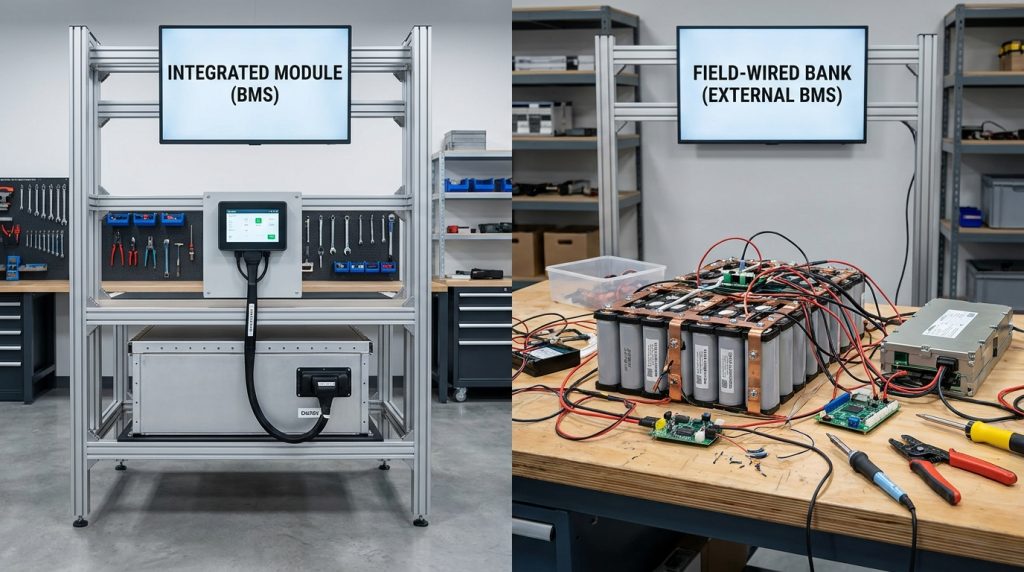
Pre-wired units reduce risk because critical sensing, balancing, contactor logic, and communication are assembled and tested as one system. Field-wired banks can work, but every cable, sensor, firmware setting, and protection threshold becomes an installer-controlled risk.
A field-wired battery bank is not automatically unsafe. It can work well in a lab, hobby setup, or controlled off-grid project. But it is usually the wrong choice for a homeowner who expects installer accountability, clean documentation, and manufacturer-backed service.
The risk is not only the cell quality. The risk is the number of small decisions that must be correct at the same time. Balance leads, sensor placement, busbar torque, polarity, communication wiring, firmware profile, and fault settings all affect how the system behaves under stress.
| Decision point | Integrated BMS module | Field-wired cell bank | Best-fit situation |
|---|---|---|---|
| Factory wiring | Pre-assembled and tested | Built on site | Integrated module for homes |
| Installer wiring responsibility | Lower | Higher | Field-wired only for skilled custom work |
| Inverter communication | Usually defined by battery maker | Must be matched manually | Integrated module for warranty-sensitive systems |
| Fault logging | Often available in module software | Depends on chosen BMS | Integrated module for service calls |
| Service ownership | Clearer manufacturer path | Can split between cell, BMS, inverter, and installer | Integrated module for homeowners |
| Warranty evidence | Easier to document | Harder to prove | Integrated module for paid installations |
The cheapest field-wired bank can become expensive after one callback. If the installer cannot prove correct sensing, balancing, communication, and protection behavior, the warranty argument becomes harder.
For a deeper safety-focused handoff, this is where the article should link to BMS protection basics. The core point is practical: factory integration does not replace professional installation, but it reduces the number of safety-critical items that must be created on site.
What protections are built into the BMS box?
An integrated BMS protects the battery by watching electrical, thermal, and operating limits in real time. It should not be treated as one simple circuit board. It is a control system that decides when the battery can charge, discharge, balance, alarm, limit current, or disconnect.
Synopsys explains that a BMS monitors battery status, helps keep the pack inside safe operating limits, and communicates with external systems. In a home ESS, that external system is usually the inverter or energy management system.
| BMS function | What it checks | Why it matters for a home ESS |
|---|---|---|
| Overvoltage protection | Cell or pack voltage too high | Prevents unsafe charging |
| Undervoltage protection | Cell or pack voltage too low | Prevents deep discharge damage |
| Overcurrent protection | Charge or discharge current too high | Reduces stress during high loads |
| Temperature protection | Hot or cold cell conditions | Helps avoid unsafe operation |
| Cell balancing | Uneven cell charge levels | Keeps capacity usable across the pack |
| SOC reporting | Estimated state of charge | Helps the inverter and user see backup capacity |
| SOH tracking | Battery health over time | Supports service and warranty review |
| Contactor or disconnect logic | When to isolate the battery | Stops operation during serious faults |
This is also where chemistry matters. LiFePO4 is widely chosen for home storage because of its stability and long cycle life, but it still needs a correct BMS. A good LiFePO4 safety comparison can help readers understand why chemistry and protection design work together.
A practical example is a 5.12 kWh home module during a high-load backup test. If the load pulls more current than the module allows, the BMS may trigger an overcurrent alarm or open the contactor. A well-integrated module can record that event, which helps the installer check load size, inverter settings, and cable sizing.
How do CAN and RS485 let the battery talk to the inverter?
CAN and RS485 carry battery status from the BMS to the inverter, but the wiring alone is not enough. The inverter must understand the battery’s protocol profile, alarm messages, charge limits, and fault states.
CAN and RS485 are communication paths. They let the battery send data such as SOC, pack voltage, current, temperature, alarm state, charge current limit, and discharge current limit. The inverter uses that information to decide how hard it can charge or discharge the battery.
This is why voltage matching alone is not enough. A 48 V battery and a 48 V inverter can still fail if the communication profile is wrong. The cable may fit, but the inverter may not understand what the battery is saying.
CAN vs RS485 in practical terms
CAN is common in many closed-loop battery and inverter systems. It is often used when fast status updates and structured device communication are needed. RS485 is also common in rack batteries and industrial systems. It can work well, but it still needs the correct wiring, address, baud rate, and protocol support.
Bosch describes battery management and disconnect systems that communicate with external control units through vehicle interfaces such as CAN. The home ESS world uses the same basic idea: the BMS must send trusted battery information to the device controlling power flow.
What the inverter needs from the BMS
The inverter needs more than a battery voltage reading. It needs to know the battery’s current limit, charge permission, discharge permission, temperature condition, alarms, and SOC. When that closed-loop data is correct, the inverter can follow the battery’s safety limits instead of guessing.
A common installer example is a 10 kWh LiFePO4 module connected through CAN. If the installer selects the wrong battery brand profile in the inverter menu, the battery may be physically connected but not properly recognized. The system may power on, yet SOC, charge limits, or alarms may not display correctly.
What happens when the BMS and inverter handshake fails?
When the handshake fails, the inverter may not trust the battery’s SOC, current limits, alarms, or temperature data. The result can be lockout, conservative charging, fault codes, or a system that runs but loses warranty-grade monitoring.
A handshake is the first successful communication between the battery BMS and inverter. It confirms that both devices can exchange usable data. If the handshake fails, the system may refuse to operate, operate in a limited mode, or show confusing readings.
Open-loop operation is not a professional shortcut for a warranty-sensitive home ESS. It may make the system run, but closed-loop CAN or RS485 communication is safer when the inverter must respect battery limits and alarms.
| Symptom | Likely cause | Installer check | Next action |
|---|---|---|---|
| No SOC reading | Wrong battery profile | Inverter battery menu | Select approved profile |
| Communication fault | CAN or RS485 cable issue | Pinout, cable, termination | Test or replace cable |
| Battery will not charge | BMS alarm or limit active | Battery logs and fault codes | Clear cause before restart |
| Inverter shows normal voltage only | No closed-loop data | Protocol support | Confirm compatibility list |
| System locks out | Failed handshake or serious alarm | BMS status and inverter code | Follow manufacturer procedure |
| SOC jumps or reads wrong | Firmware or profile mismatch | Firmware versions | Update or change profile |
Soft failure vs hard lockout
A soft failure means the system still runs, but it loses useful data. For example, an inverter may show battery voltage but no accurate SOC. That can confuse backup planning because the homeowner does not know how much usable energy remains.
A hard lockout is more serious. The battery may open its contactor, refuse charge, refuse discharge, or show a fault until the cause is corrected. In one practical RS485 example, swapped A/B lines can create a communication fault even when battery voltage looks normal. The fix starts with cable checks, not battery replacement.
How does integration change warranty, service, and troubleshooting?
Integration improves warranty confidence because the battery manufacturer can define the wiring, firmware, protection thresholds, and communication behavior as one tested module. It does not guarantee coverage if the inverter profile, installation, or operating limits are wrong.
Warranty problems often start when responsibility is unclear. In a field-wired system, the cell supplier, external BMS supplier, inverter supplier, and installer may each point to another part of the system. A pre-built module gives the battery maker more control over the parts inside the box.
That matters during service. If a BMS alarm records overcurrent, high temperature, or a communication fault, the installer can work from logs instead of guesses. A homeowner also gets a clearer answer: the module either operated inside approved limits or it did not.
A good service checklist should confirm:
- Approved inverter model and battery profile
- CAN or RS485 communication status
- Firmware version on both devices
- Battery alarm history and fault codes
- Charge and discharge current limits
- Installation environment and temperature range
- Warranty terms for parallel expansion
This does not mean every claim gets approved. If the installer uses an unsupported inverter, ignores fault codes, or runs the module outside approved limits, the warranty can still be at risk. For buyers comparing chemistry and long-term ownership, LiFePO4 benefits are only part of the decision. Service evidence matters too.
When can a DIY cell-level pack still make sense?
A DIY cell-level pack can make sense when the buyer accepts full responsibility for design, wiring, testing, and safety. That usually means hobby projects, controlled lab work, experimental off-grid builds, or non-warranty systems where the owner has the skills to diagnose faults.
It is not the best fit for a homeowner who wants a clean installation, clear support path, and simple warranty review. A DIY pack may save money at purchase, but it also shifts more safety and documentation work onto the builder or installer.
| Buyer situation | Better fit | Why |
|---|---|---|
| Homeowner wants backup power with support | Integrated BMS module | Clearer service and warranty path |
| Installer wants repeatable jobs | Integrated BMS module | Less custom wiring and fewer callbacks |
| Hobby builder wants full control | DIY cell-level pack | Allows custom design and testing |
| Remote off-grid user with technical skill | Depends on support needs | DIY can work if risk is accepted |
| Warranty-sensitive residential project | Integrated BMS module | Easier to prove approved installation |
A simple example shows the tradeoff. An installer compares loose cells, an external BMS board, manual busbars, and a pre-built 5.12 kWh module. The loose-cell path may look cheaper at first. But the installer now owns sensor placement, balance wiring, torque checks, communication setup, and fault proof.
What should installers verify before specifying an integrated BMS unit?
Installers should verify inverter compatibility, protocol support, firmware version, communication wiring, fault visibility, and expansion rules before the battery reaches the site. A safe module can still create problems if it is paired with the wrong inverter profile.
UL Solutions describes UL 9540 as covering energy storage system safety, including protection, control, and communication between devices. That fits the real job site concern: the battery, inverter, and protection system must work together as an approved system.
Use this pre-purchase and commissioning checklist:
- Confirm the inverter appears on the battery maker’s compatibility list.
- Check whether the system uses CAN, RS485, or another approved method.
- Confirm the exact battery profile needed in the inverter menu.
- Verify communication cable pinout before energizing the system.
- Check baud rate, address, or DIP switch settings where required.
- Confirm battery and inverter firmware versions.
- Review fault code visibility in the inverter or battery software.
- Confirm charge and discharge current limits.
- Check allowed parallel expansion rules.
- Confirm required breakers, cables, and installation spacing.
- Save screenshots or logs after commissioning.
Do not treat this checklist as paperwork. It protects the installer. If a callback happens later, clean commissioning records can show that the battery and inverter were paired, configured, and tested correctly.
What documents can prevent shipping, customs, or commissioning delays?
The right documents can reduce preventable delays before the battery even reaches the job site. Ask suppliers for UN38.3 test summary, SDS or MSDS, packing declaration, invoice description, and classification support before shipment.
A BMS-integrated-unit-specific customs delay process could not be verified in the research brief. Treat the unit as part of a lithium battery product unless a customs broker, carrier, or local authority confirms another handling path.
For air transport, lithium battery rules can include state-of-charge limits. A Federal Register lithium battery transport update discusses 30 percent state-of-charge limits for certain lithium-ion batteries moved by air. Tariff timing can also matter for battery imports, and USTR materials address tariff changes for certain lithium-ion battery categories.
A practical supplier document pack should include:
- UN38.3 test summary
- SDS or MSDS
- Packing declaration
- Commercial invoice with clear product description
- HS or HTS classification support
- Battery capacity and voltage information
- Manufacturer warranty and installation manual
- Inverter compatibility sheet
This is not a replacement for broker advice. It is a buyer checklist that helps prevent avoidable confusion during shipping, receiving, and commissioning.
Getting the Next Step Right
Battery Management System integrated units are usually the better choice for homeowner-facing ESS projects because they reduce hidden installation risk. The right next step is not to buy the highest-capacity module first. Start with inverter compatibility, communication protocol, firmware support, warranty terms, and clear commissioning records.
If the project is a professional home installation, choose a pre-wired module that can prove how it protects the battery and talks to the inverter. DIY packs still have a place, but they belong where the owner accepts the extra design and support responsibility.
Frequently Asked Questions
What is a battery management system BMS?
A BMS is the control and protection system that monitors a rechargeable battery pack and keeps it inside safe operating limits. In a home battery, it tracks voltage, current, temperature, SOC, SOH, balancing, alarms, and communication with the inverter.
What are the primary functions of a battery management system?
The primary functions are monitoring, protection, state estimation, balancing, thermal management, and communication. In an integrated unit, these functions are coordinated inside one module instead of being assembled from separate field-wired parts.
Why is cell balancing important in a BMS?
Cell balancing keeps cells at similar charge levels so one weak or overcharged cell does not limit the full pack. This helps preserve usable capacity, reduce stress, and support longer battery life.
How does a BMS estimate state of charge?
A BMS estimates state of charge by using battery measurements such as voltage, current, temperature, and operating history. The inverter uses that SOC value to decide charging, discharging, backup behavior, and user display information.
What protections does a battery management system provide?
A BMS protects against unsafe conditions such as overvoltage, undervoltage, overcurrent, overheating, low-temperature charging, short circuits, and cell imbalance. In integrated modules, those protections can also trigger alarms or disconnect logic.
What happens if the battery management system fails?
If the BMS fails or cannot communicate correctly, the battery may stop charging, stop discharging, report wrong SOC, trigger alarms, or open its contactors. A professional installer should treat repeated BMS faults as a system-level safety issue.
What causes BMS failure?
Common causes include wrong inverter protocol, damaged communication cable, incorrect wiring, firmware mismatch, overheated electronics, sensor faults, moisture damage, or operation outside approved limits. The fastest diagnosis usually starts with logs, fault codes, cable checks, and inverter profile confirmation.

-

 OEM Residential Energy Storage Solutions: Passive vs. Active Cell Balancing
2026-09-30
-
 Smart Home Battery with BMS Communication: Cybersecurity and BMS Safety
 -
 10kWh Home Battery Backup System: Is 90% DoD Better for Daily Solar Storage?
2026-09-29
-
 Integrated Home Energy Storage System 150–430V MPPT Design
2026-09-28
-
 LiFePO₄ Residential Backup Battery SOC Accuracy in Parallel Systems
Share this:





.svg)






-899.svg)


