




Campus Battery Energy Storage System for Universities and Multi-Building Sites
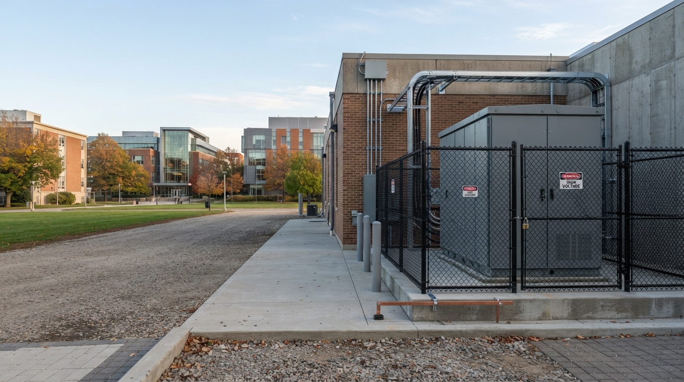
Campus battery energy storage systems — often called campus BESS — help universities and other multi-building sites manage peak electricity demand, use more of their on-site solar energy, support electric vehicle charging, and keep critical buildings online during outages. If you are just beginning to evaluate storage for your site, our Comprehensive Guide to Commercial & Industrial Energy Solutions provides the broad context. This guide focuses specifically on what campuses need to consider.
What Is a Campus Battery Energy Storage System?
A campus BESS stores electrical energy in batteries and releases it strategically to serve multiple buildings on one site. Unlike a single-building backup battery, a campus system is designed around the combined load of many facilities: lecture halls, laboratories, dormitories, administration buildings, data centers, sports facilities, and increasingly, EV charging hubs.
At the system level, every campus BESS includes:
- Battery hardware — cells grouped into modules, modules arranged into racks, and racks housed in cabinets or containers.
- A battery management system (BMS) — protects the battery by monitoring voltage, current, temperature, and cell balancing.
- A power conversion system (PCS) or inverter — converts DC battery power to the AC power used by campus equipment.
- An energy management system (EMS) — coordinates when the battery charges, discharges, and responds to campus or utility signals.
- Monitoring and protection systems — provide alarms, data, thermal management, and fire-safety functions.
What makes a campus BESS different from a backup battery is the planning. The system is sized and dispatched based on the range of operating objectives the campus wants to achieve.
Why Universities and Multi-Building Sites Install Battery Storage
Campuses install BESS for four main reasons, and most projects combine more than one. These objectives matter because they drive every later decision about architecture, power rating, energy capacity, and control strategy.
Peak Shaving and Demand-Charge Management
Utility charges are often based on the highest 15- or 30-minute average kW demand during a billing period. A campus BESS can detect a peak forming and discharge just enough power to flatten that demand spike.
The result is lower demand charges, which on many commercial tariffs represent a large share of the monthly bill. Load shifting is a related strategy: the battery charges when energy prices are low and discharges when prices or demand are high.
Whether peak shaving is financially attractive depends on the campus tariff, the peak window, and the shape of the daily load curve. This is why a load study matters before sizing. The Burns Group’s engineering guidance for universities makes the same point — the business case starts with the campus electricity profile, not with the battery.
Solar Self-Consumption and Export Control
Campuses that have installed solar PV often find that midday generation exceeds what the buildings can use. Without storage, that excess is exported to the grid for little or no credit. Some campuses also face export limit constraints imposed by the utility or local interconnection rules.
A BESS can charge from surplus solar during the middle of the day and discharge in the evening or during the campus peak. The 900 kW / 1,080 kWh system at Cranfield University is a useful example: the battery was installed primarily to capture more solar energy and manage the site’s import and export of power. The same principle applies on many university campuses where PV output and building load do not align naturally.
Resilience, Microgrid Support, and Critical Loads
No campus wants to lose power in a research laboratory, a health center, or a data center that supports online learning and administration. A BESS can keep selected critical loads running during a grid outage, but only if the system is designed for that purpose.
Resilience planning starts with defining critical loads:
- Life-safety systems and emergency lighting.
- Laboratories with samples, refrigerators, or venting requirements.
- Data centers and core network infrastructure.
- Health and wellness centers.
- Water pumping and building HVAC controls.
The backup runtime depends on two numbers: the size of the connected critical load in kW and the usable energy in the battery in kWh. If a campus needs 300 kW of critical loads for four hours, the system must deliver roughly 1,200 kWh of usable energy before losses and reserve margins.
In a broader microgrid design, the BESS works with the EMS, existing generators, and transfer switching to isolate the campus from the grid and operate in islanded mode. This is technically possible but requires coordinated controls and utility approval. It is not an automatic feature of every BESS.
EV Charging Support and Load Growth
Electric vehicle charging is one of the fastest-growing campus loads. EV chargers draw high power in short bursts, especially when several vehicles plug in simultaneously. If a campus is already close to its transformer or feeder capacity, adding a 150 kW charging hub may trigger an expensive utility upgrade.
A BESS can charge during low-load periods and discharge while vehicles are charging, reducing the draw on the campus connection. It can also allow the campus to install more chargers than the incoming electrical service would otherwise support. This application must be included in sizing from the start because EV load is large relative to most building loads. See our guide on battery storage for ev charging stations for a deeper look at that topic.
Centralized vs. Distributed Campus Storage
Campuses typically choose between two architectures: one central BESS or several smaller building-level systems.
| Comparison Factor | Centralized BESS | Distributed BESS |
|---|---|---|
| Number of systems | One or a few large units | Many smaller units |
| Location | Central electrical yard or substation area | Individual buildings or building clusters |
| Typical format | Containerized or large-cabinet systems | Smaller cabinets or indoor racks |
| Interconnection | One central connection point | Multiple connection points |
| Resilience | Campus-wide if the central point serves critical feeders | Localized to each served building |
| Siting complexity | Requires land, transformer, and switchgear space | Requires space in each building or nearby |
| Operational coordination | Simpler, one EMS interface | More assets to monitor and maintain |
| Best fit | Campus-wide peak shaving, microgrid, PV integration | Building-specific resilience or limited construction space |
Centralized BESS
A centralized system is usually container-based or housed in a dedicated electrical area. It connects to the campus through one main point of interconnection, which means the transformer, switchgear, and protection are all concentrated in one location.
This architecture works well when the campus has a single dominant feeder, a central utility yard, or a site-wide microgrid plan. It also simplifies operation because the EMS controls one large asset rather than a fleet of smaller units. The University of York’s BESS project illustrates what this can mean at practical level: the system is connected behind a transformer and switchgear, which are just as important as the battery itself.
Distributed Building-Level BESS
A distributed approach places smaller battery cabinets at individual buildings or campus clusters. This is often driven by space constraints or by a need to protect specific facilities with their own local backup.
The trade-off is complexity. Every distributed unit needs its own enclosure, thermal management, communication connection, and maintenance plan. Achieving campus-wide peak shaving with distributed units also requires the EMS to coordinate multiple assets.
Choosing the Right Architecture
There is no universal winner. The right architecture depends on campus constraints, load concentration, and operating objectives:
- If the goal is site-wide peak shaving and utility cost reduction, a centralized system is easier to manage.
- If the goal is protecting specific laboratories or data centers independently, distributed systems give cleaner backup boundaries.
- If land and electrical room space are scarce, distributed cabinets may be the only feasible option.
- If a campus microgrid is planned, the interconnection philosophy will determine whether one central point or several distributed points make more sense.
The same logic applies to multi-building industrial, corporate, and healthcare campuses. Compare a site-wide resilience strategy with the airport microgrid approach described in our battery storage for airport microgrid guide — the planning principles are similar even though the operational requirements differ.
How to Size a Campus Battery Energy Storage System
Sizing a campus BESS is not about picking a standard kW or kWh number. It is about translating campus objectives into technical requirements.
Power and Energy: kW vs. kWh
The most common sizing mistake in battery storage is confusing power with energy.
- Power (kW) is the rate at which the battery can charge or discharge. It determines what size load the system can serve at any instant.
- Energy (kWh) is the amount the battery can store and deliver over time. It determines how long the system can serve that load.
A simple relationship: usable energy in kWh divided by the connected load in kW gives an approximate runtime in hours. So a system with 600 kWh of usable energy serving a 200 kW load can run for roughly three hours, before losses and reserve settings are considered.
The battery’s electrical design also matters. Modules are built with cells that have a nominal voltage (V) and amp-hour capacity (Ah). The pack voltage and Ah determine the system’s DC energy in kWh. The PCS and inverter then determine the AC power in kW the campus can actually use. Keep these numbers separate — a battery-vendor datasheet may list module voltage and capacity, but the installed system’s power and energy at the AC side depend on the full configuration.
Critical Loads and Backup Runtime
If resilience is a goal, the sizing process should follow these steps:
- List the critical loads that must stay online during an outage.
- Estimate the operating kW of those loads.
- Decide how many hours of runtime the campus requires.
- Multiply kW by hours to find required usable kWh.
- Add margin for efficiency losses, degradation, and a reserve that prevents deep discharging.
The U.S. Department of Energy’s BESS evaluation methodology and procurement checklist both emphasize this distinction between energy capacity and performance over time. Capacity degrades with age, so the initial usable energy should account for the performance expected at the end of the warranty period.
Solar, EV Charging, and Future Load Growth
A campus BESS sizing study should include:
- Solar generation profiles — when the PV system produces surplus and when it is needed.
- Export limits — whether the utility permits any export at all.
- EV charging demand — current and planned chargers.
- Building electrification — heat pumps, electric kitchens, and new construction all grow the load curve.
The National Renewable Energy Laboratory’s work on PV-plus-storage integration at its Flatirons Campus shows how closely inverter controls, PV production, and battery dispatch must be coordinated. A campus with heavy solar and EV load cannot size the battery in isolation from those systems.
Common Campus Sizing Mistakes
- Sizing only by kWh while ignoring peak kW requirements.
- Using nominal capacity instead of usable capacity.
- Forgetting that capacity degrades over the life of the system.
- Failing to define which loads must run during an outage.
- Ignoring EV charging growth and building electrification.
- Choosing a battery before the operating objectives are written down.
None of these errors are unusual. All of them are avoidable with a structured site assessment.
Key Components of a Campus BESS
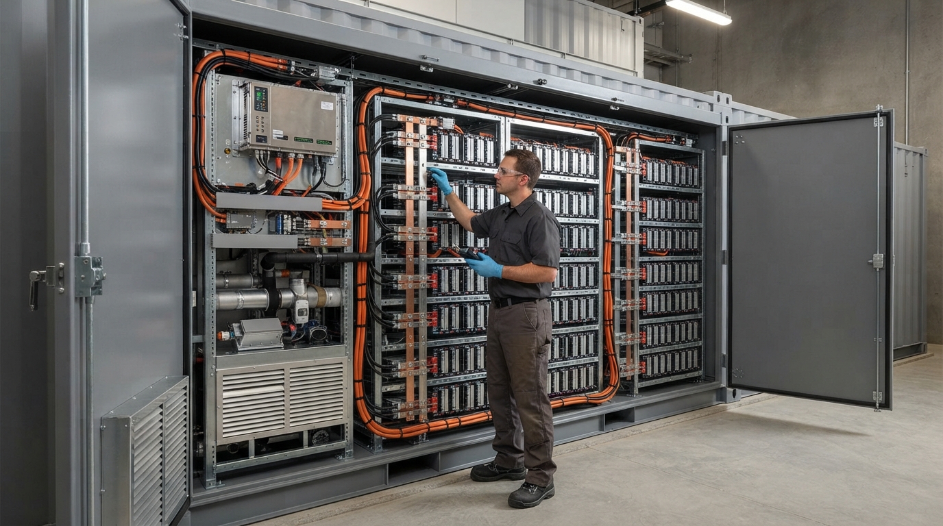
Understanding what is inside a BESS helps you compare supplier proposals and ask the right technical questions.
Battery Cells, Modules, Racks, and Cabinets
The physical battery is built in layers:
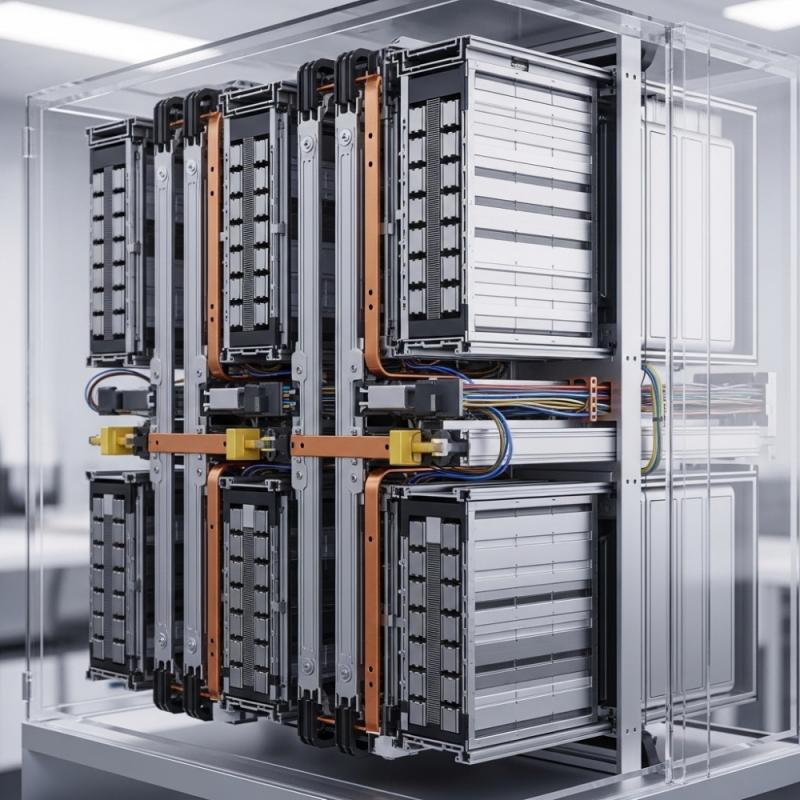
- Cells — the smallest storage unit. Lithium iron phosphate (LiFePO₄ or LFP) is a common chemistry in stationary storage because of its safety profile, cycle life, and tolerance of high temperatures.
- Modules — groups of cells connected in series or parallel.
- Racks — multiple modules arranged in a frame.
- Cabinets or containers — enclosures that house racks and their thermal, monitoring, and safety equipment.
The connection of cells and modules determines the system’s nominal voltage and its capacity in Ah and kWh. This is why a module specification cannot be treated as a whole-system specification.
BMS, EMS, PCS, Inverter, and Monitoring
The intelligence layer of a campus BESS is what makes the battery useful:
- BMS protects the battery by monitoring cell voltage, temperature, current, and state of charge. It manages cell balancing and opens protection paths when conditions are unsafe.
- EMS acts as the site-level brain. It decides when to charge and discharge based on campus load, utility prices, solar output, EV demand, and generator status.
- PCS or inverter converts DC power from the battery into AC power for campus loads. The power rating of the PCS is the main constraint on how fast the system can respond.
- Monitoring platforms record performance, raise alarms, and give operators remote visibility. Communication protocols matter when the BESS must talk to the campus EMS, the utility, or third-party control systems.
The U.S. Department of Energy’s BESS technical specification guidance for federal sites requires explicit definitions of commissioning, monitoring, and communication requirements. The same rigor applies to a university project. For a more general look at C&I system architecture, see our explanation of the ci energy storage system.
Thermal Management, Enclosures, and Fire Safety
Batteries generate heat during charge and discharge, and temperature extremes accelerate degradation. Most large systems use either forced air cooling or liquid cooling to manage the temperature of the cells and modules.
The enclosure protects the battery from weather, dust, and physical damage, with an IP rating that indicates its level of ingress protection. Outdoor containers generally require more robust thermal and fire-safety engineering than indoor cabinets.
Fire safety is a serious engineering consideration rather than a marketing feature. Thermal runaway is a known lithium-battery hazard, and installation design must account for detection, suppression, ventilation, separation from buildings, and emergency access. NFPA 855 in the United States and equivalent local codes elsewhere set installation requirements. UL Solutions describes UL 1973, UL 9540, and UL 9540A as complementary components of a regulatory framework: the first addresses the battery module or system, the second the complete energy-storage system, and the third the fire-propagation test method. Your local authority having jurisdiction decides which codes and standards apply to your project.
Safety, Codes, and Grid Interconnection
A campus BESS cannot be treated as an appliance. It is a grid-connected electrical asset with its own safety and approval requirements.
Safety Standards and Site Design
The relevant standards depend on where the campus is located. In North America, NFPA 855 governs installation safety, while UL 1973 and UL 9540 address product- and system-level safety. In other regions, IEC standards and local regulations may apply. Whatever the market, the equipment should have certificates or test reports that match the exact models being supplied.
Site design must include:
- Setback distances from structures and property lines.
- Ventilation and thermal management requirements.
- Fire detection and suppression equipment.
- Emergency shutoff and disconnection points.
- Access for maintenance and emergency responders.
Sandia National Laboratories maintains a codes and standards resource for energy-storage safety that is useful for understanding how these requirements interact at a national level. It does not replace a project-specific review by the authority having jurisdiction.
Grid Interconnection and Utility Approvals
Connecting a BESS to the campus electrical network is normally only part of the process. The point where the system connects to the utility network determines much of the required equipment:
- A transformer may be needed to step voltage between the battery system and the campus distribution network.
- Switchgear and protection relays must be coordinated with utility settings.
- Export limits may restrict how much power the BESS can send to the grid.
- Islanding requires control logic and utility approval, and is never assumed.
The utility’s interconnection process will typically require an application, a technical study, and a formal agreement before the system can operate in parallel with the grid.
Campus BESS Procurement and Supplier Evaluation
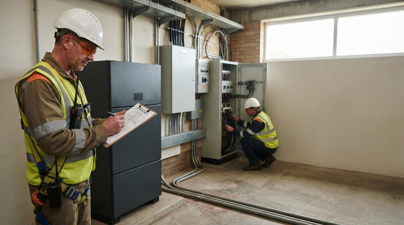
Once the campus has defined its objectives and a preliminary system size, the purchasing process begins. The most important step is understanding who is responsible for what.
Battery Supplier vs. System Integrator
A battery manufacturer supplies the hardware. An integrator or EPC designs the complete system, installs it, connects it to the campus, commissions it, and often provides ongoing service. These roles are not interchangeable.
Some suppliers offer complete integrated systems, and some integrators purchase batteries from multiple vendors. The buyer must define in the request for proposal whether it is purchasing hardware only, a complete system, or a fully installed and commissioned solution.
| Responsibility | Battery Supplier | Integrator / EPC |
|---|---|---|
| Supply battery cells, modules, racks, BMS | Yes | Usually through supplier |
| Provide PCS, inverter, EMS, monitoring | Possibly | Usually |
| Electrical design and single-line diagram | No | Yes |
| Permits and utility interconnection | No | Yes |
| Installation and commissioning | No | Yes |
| Ongoing maintenance and monitoring | Optional | Often |
VoltaLink Battery, for example, is positioned as an energy-storage manufacturer and solution provider serving commercial, industrial, household, and outdoor storage markets. Whether a particular supplier also provides installation or commissioning must be confirmed for each project. Do not assume a hardware supplier is also your EPC.
Procurement Checklist and Required Documentation
The U.S. Department of Energy’s Battery Energy Storage System Procurement Checklist recommends that buyers address site physical location, interconnection point, site ownership, construction support, monitoring, and applicable codes and standards. At a campus scale, the procurement documents should include:
- Complete datasheets with consistent units: V, Ah, kWh, kW, and A.
- A single-line diagram showing the BESS and its interconnection.
- BMS and EMS descriptions, including alarm points and communication protocols.
- Model-specific certificates and test reports.
- Installation, operation, and maintenance manuals.
- Commissioning procedures and acceptance-test criteria.
- Spare-parts strategy and training plan.
Warranty, O&M, and Lifecycle Questions
A battery is a long-lived asset, and its performance changes over time. Before awarding a contract, ask these questions:
- What is the warranty term, and what capacity-retention guarantee does it include?
- How will degradation be measured, and is the testing method defined?
- What maintenance schedule is required, and who performs it?
- How are software updates and cybersecurity handled?
- What is the emergency-response procedure if a cell fails?
- Are remote monitoring and troubleshooting included?
The DOE’s BESS technical specification guidance treats capacity retention, commissioning, and performance evaluation as core contract elements. Your campus procurement should do the same.
Summary and Next Steps
A campus BESS can be a strong investment when it is sized around the site’s real objectives: peak-demand reduction, solar optimization, resilience, EV integration, or microgrid operation. The key is to work through the planning process in order — define the problem, choose the architecture, size the system, and then evaluate suppliers on verified evidence rather than marketing claims.
If your campus is ready to explore options, start by gathering a full year of interval load data, listing critical loads, and mapping your solar and EV plans. Then compare the commercial backup energy storage solutions offered by different providers. A qualified supplier or systems integrator can turn that data into a conceptual design and a realistic budget.

-

 OEM Residential Energy Storage Solutions: Passive vs. Active Cell Balancing
2026-09-30
-
 Smart Home Battery with BMS Communication: Cybersecurity and BMS Safety
 -
 10kWh Home Battery Backup System: Is 90% DoD Better for Daily Solar Storage?
2026-09-29
-
 Integrated Home Energy Storage System 150–430V MPPT Design
2026-09-28
-
 LiFePO₄ Residential Backup Battery SOC Accuracy in Parallel Systems
Share this:





.svg)






-899.svg)


