




UL9540 Listed Energy Storage System: What It Means for Residential Battery Safety
A residential battery can store 10–20kWh or more only a few meters from living spaces, vehicles, electrical panels, and other equipment. For that reason, battery safety cannot be judged only by cell chemistry or a battery-level certificate.
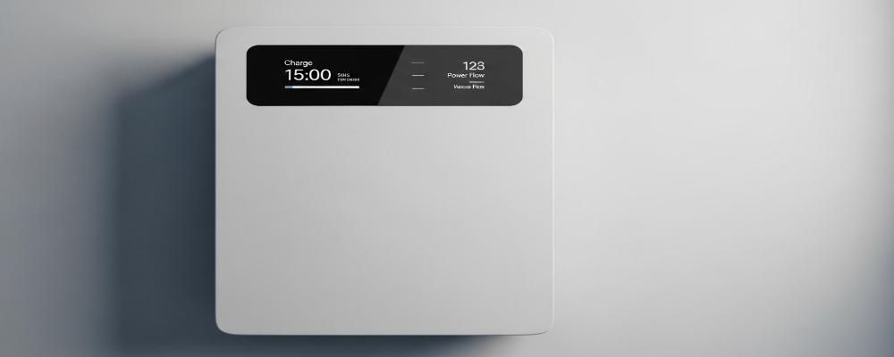
What is UL 9540?
UL 9540 is the North American safety standard for Energy Storage Systems and Equipment (ESS). UL 9540 is a system-level safety certification standard and not just a battery performance standard.
UL 9540 oversees the safety of the entire energy storage system comprising the following:
• Battery packs and BMS
• Inverter or PCS
• Charging and discharging controls
• Overcurrent and fault protection
• System component communications
• Housing and wiring, controls, and interaction with the Grid
For residential batteries, a UL9540 Listed Energy Storage System implies that the complete configuration of the ESS has been assessed against UL 9540 standards. A battery which conforms to UL 1973 on its own does not imply that the complete battery and inverter system is UL9540 Listed.
In simple terms, UL 1973 focuses mainly on the battery, while UL 9540 focuses on whether the whole energy storage system works safely together. For residential buyers, this system-level perspective is important because many serious fault conditions involve interaction between components rather than failure of one component in isolation.
The practical question is not simply “Is the battery safe?” It is:
Can the complete ESS detect an abnormal condition, limit it, isolate it, and prevent one fault from developing into a larger system event?
Why UL9540 Goes Beyond Battery-Level Safety
UL1973 and UL9540 serve different purposes. UL1973 addresses batteries used in stationary applications, while UL9540 evaluates the energy storage system as an integrated product.
A typical residential ESS safety chain looks like:
Cells → BMS → Contactors/Fuses → DC Bus → PCS/Inverter → AC Distribution
A battery-level evaluation cannot by itself confirm how the inverter responds when the BMS reports excessive temperature, how charging stops after an overvoltage event, or what happens when communication is lost.
This is where a UL9540 Listed Energy Storage System becomes relevant: protection must work across the entire power and control path.
How a Residential ESS Should React to a Fault
Good safety engineering is based on coordinated fault response rather than a long list of independent “protection features.”
Overtemperature
When cell temperature exceeds an allowable limit, the expected control sequence may involve:
• Temperature sensing inside the battery
• BMS identification of the abnormal condition
• Reduction of allowable charge/discharge current
• Transmission of updated limits to the PCS
• Controlled shutdown if temperature continues to rise
• Electrical isolation through the protection path
Overvoltage or Overcharge
The BMS should not rely only on a fixed inverter voltage setting. Cell-level voltage information must be used to prevent individual cells from exceeding defined limits.
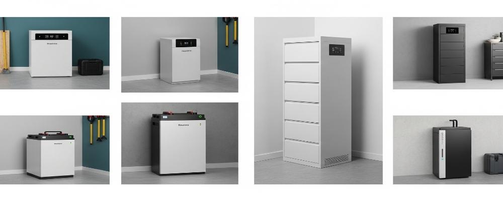
Overcurrent and Short Circuit
Protection becomes particularly important in high-current residential batteries. The battery, fuse or breaker, contactor, cabling, busbar, and inverter must all be coordinated around the expected current and fault-current conditions.
| Fault Condition | Detection Point | Expected System Action |
| Cell overvoltage | BMS cell monitoring | Reduce or stop charging |
| High temperature | Temperature sensors | Derate current or shut down |
| Overcurrent | BMS/current sensor | Current limitation or isolation |
| Short circuit | Protection devices | Rapid interruption |
| Communication loss | BMS/PCS | Defined fail-safe state |
This coordinated Detect → Communicate → Limit → Disconnect sequence is more meaningful than simply stating that an ESS has a “smart BMS.”
LiFePO₄ Does Not Eliminate the Need for System Safety
LiFePO₄ is widely used in residential storage because of its electrochemical and thermal characteristics, but chemistry is only one layer of protection.
A UL9540 Listed Energy Storage System still needs to address:
• Cell voltage imbalance
• Excessive charging current
• Internal temperature rise
• External short circuits
• Isolation failures
• PCS control errors
• Communication faults
• Thermal propagation
For example, the residential platform referenced by VoltaLink uses 51.2V 314Ah LiFePO₄ batteries with 16.07kWh rated energy. From a safety-engineering perspective, the important issue is not simply that LiFePO₄ is used, but how approximately 16kWh of stored electrical energy is controlled during both normal operation and fault conditions.
High Discharge Current Requires Matching Protection
Battery current is another specification that should be interpreted as a safety parameter.
The referenced design supports 150A continuous charging and up to 300A continuous discharge.
At this current level, buyers should examine the complete DC path:
• BMS current limit
• Contactor rating
• Fuse or breaker interruption capacity
• Cable cross-section
• Terminal and busbar capability
• Inverter battery-input current
• Thermal rise under sustained load
A high current rating is useful only when every component in the current path has been designed and protected accordingly.
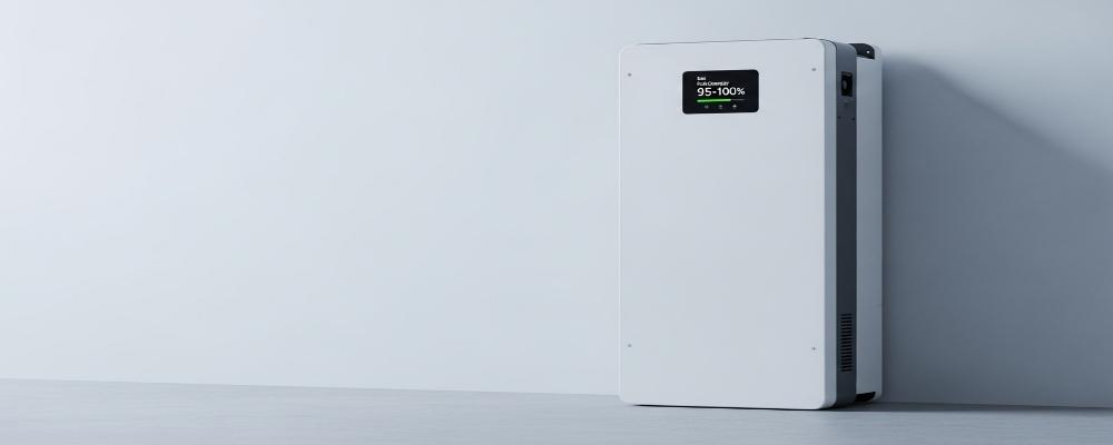
Why Parallel Expansion Changes the Safety Model
A modular ESS is often discussed only in terms of backup time. In reality, adding batteries changes several safety variables simultaneously.
The referenced VoltaLink architecture supports up to six units in parallel, taking nominal capacity from 16.07kWh to approximately 96kWh.
Moving from one battery to multiple parallel batteries can change:
• Stored energy: More energy is present at the installation.
• Available current: Parallel paths may increase system current capability.
• Protection coordination: Cables, busbars and disconnect devices may require different ratings.
• Fault isolation: One failed module should not compromise the entire bank.
• BMS architecture: Master/slave communication becomes more important.
• Certification scope: Buyers must verify whether the intended multi-battery configuration is covered.
Therefore, “expandable to six batteries” should never be treated only as a capacity feature.
CAN and RS485 Are Part of the Safety Chain
Modern residential batteries commonly use CAN or RS485 communication. VoltaLink’s referenced platform includes CAN, RS485, and RS232 interfaces.
These interfaces become safety-relevant when the BMS continuously communicates operating limits to the inverter.
Important data may include:
• State of charge
• Battery voltage
• Cell or pack temperature
• Maximum charge current
• Maximum discharge current
• Alarm status
• Shutdown commands
However, having a CAN port does not mean two devices are automatically compatible. The BMS and PCS must use compatible protocol definitions and fault-handling logic.
This is why buyers evaluating a UL9540 Listed Energy Storage System should verify the exact battery-inverter configuration rather than assuming that any CAN-enabled inverter can be substituted.
UL9540, UL9540A and UL9540B Address Different Risks
These standards and test methods should not be treated as interchangeable.
| Standard / Test | Main Safety Question |
| UL1973 | Is the stationary battery designed to applicable battery safety requirements? |
| UL9540 | Does the complete ESS operate safely as an integrated system? |
| UL9540A | What happens during thermal runaway and fire propagation? |
Passing a UL9540A test does not mean that fire is impossible, and UL9540A should not be described as a substitute for UL9540 listing. Each addresses a different layer of ESS safety.
Installation Is Still Part of Residential Battery Safety
Even a UL9540 Listed Energy Storage System must be installed within its defined environmental and electrical conditions.
For example, the referenced VoltaLink configuration is specified as IP20 for indoor use. Buyers should therefore not assume suitability for exposed outdoor installation.
Before installation, verify:
• Indoor or outdoor approval
• Temperature limits
• Equipment clearances
• Overcurrent protection
• DC disconnect location
• Cable routing
• Service access
• Battery quantity and spacing
• Local electrical and fire-code requirements
Commissioning should also test BMS-to-inverter communication, current limits, alarm behavior, and controlled shutdown—not merely confirm that the system can charge and discharge.
Final Words
For residential projects evaluating a UL9540 Listed Energy Storage System, VoltaLink can use project information such as inverter architecture, required capacity, current demand, installation location, and expansion plan to support configuration discussions before procurement. This makes it easier to evaluate the complete ESS rather than judging safety from the battery specification alone.
FAQs
Q1. What battery chemistry does VoltaLink use for its residential energy storage system?
The VoltaLink residential battery uses LiFePO₄ (lithium iron phosphate) chemistry with a nominal voltage of 51.2V and a rated capacity of 314Ah.
Q2. How much energy does the VoltaLink 51.2V 314Ah battery store?
One battery provides 16.07kWh of rated energy. Actual usable backup time depends on the connected load, inverter efficiency, reserve settings, and operating conditions.
Q3. What certifications are listed for the VoltaLink residential battery?
VoltaLink’s supplied product offers UL1973, UL9540, UL9540A, and IEC62619. Buyers should verify that the exact model and battery-inverter configuration are covered by the documentation required for their project.
Q4. What is the charging and discharging capability?
The battery is specified for 150A continuous charging, 150A standard discharge, and up to 300A continuous discharge. The inverter, cables, busbars, and protection devices must also be rated appropriately.
Q5. Can multiple VoltaLink batteries be connected together?
Yes. The referenced design supports up to six batteries in parallel, increasing nominal storage capacity to approximately 96kWh. System current, BMS coordination, inverter limits, and certification scope should be checked when expanding.

-

 OEM Residential Energy Storage Solutions: Passive vs. Active Cell Balancing
2026-09-30
-
 Smart Home Battery with BMS Communication: Cybersecurity and BMS Safety
 -
 10kWh Home Battery Backup System: Is 90% DoD Better for Daily Solar Storage?
2026-09-29
-
 Integrated Home Energy Storage System 150–430V MPPT Design
2026-09-28
-
 LiFePO₄ Residential Backup Battery SOC Accuracy in Parallel Systems
Share this:





.svg)






-899.svg)


