




High-Rate Discharge in Data Center UPS Battery Backup Systems Explained
A Data Center UPS Battery Backup is often selected by runtime: determine the critical load, choose the required backup minutes, then calculate battery capacity. That calculation is necessary, but it is incomplete.
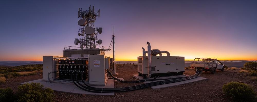
During a utility failure, the battery must also deliver enough DC power and current to support the UPS without excessive voltage sag or triggering BMS protection. A battery may therefore contain enough kWh for the required runtime but still be unsuitable for a high-load UPS.
For lithium-based UPS systems, high-rate discharge should be evaluated as a complete electrical chain:
Cell → Battery Module → BMS → DC Cabling → Protection Devices → UPS DC Bus → IT Load
Why Battery Capacity Alone Does Not Define UPS Performance
Battery capacity answers an energy question:
• How long can the battery operate?
• High-rate discharge answers a power question:
• Can the battery supply the required current while keeping voltage inside the UPS operating window?
For a constant-power UPS load:
P = V × I
As battery voltage falls, the required current rises.
For example, a 6 kW DC load requires approximately:
| Battery Voltage | Approx. Current for 6 kW |
| 54 V | 111 A |
| 48 V | 125 A |
| 42 V | 143 A |
| 37.5 V | 160 A |
This illustrates an important Data Center UPS Battery Backup design issue: sizing current only at nominal voltage can underestimate the current required near the lower end of the battery discharge range.
UPS compatibility therefore has to be checked at the minimum usable battery voltage, not only at 48V nominal.
C-Rate Is Useful, but It Is Not the Whole Specification
C-rate relates discharge current to battery capacity:
C-rate = Discharge Current ÷ Rated Capacity
A 150Ah battery supplying 150A is operating at approximately 1C.
For instance, the VoltaLink 48V 150Ah rack-mount battery delivers a 150A continuous discharge current, supplying a substantial 7.2 kW of nominal DC power per individual module.
However, a professional Data Center UPS Battery Backup specification should not stop at “1C discharge.”
Engineers should also verify:
• Continuous discharge current;
• Peak discharge current;
• Permitted peak duration;
• Battery voltage under high-current load;
• DC internal resistance;
• BMS overcurrent threshold and delay;
• Low-voltage cutoff;
• Temperature derating;
• SOC-dependent discharge performance.
A battery capable of 300A for five seconds is not equivalent to one capable of 300A for five minutes.
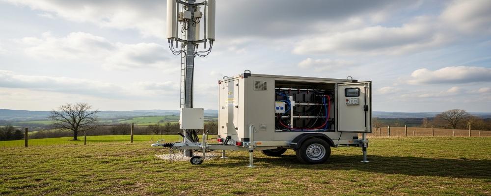
Voltage Sag Can End Backup Before the Battery Is Empty
When current rises, voltage drops across the resistance of the entire DC path.
A simplified relationship is:
Voltage Drop ≈ Current × DC Resistance
Resistance exists not only inside the cells, but also in:
• Cell interconnections;
• Busbars;
• BMS switching components;
• Terminals;
• Cables;
• Breakers and fuses;
• Rack-to-UPS connections.
At high current, these losses also generate heat approximately according to I²R.
This means doubling current can produce roughly four times the resistive heating if resistance remains unchanged.
For a Data Center UPS Battery Backup, excessive voltage sag can cause three different shutdown mechanisms:
- Battery terminal voltage falls below the UPS DC input limit;
- The BMS reaches its low-voltage protection threshold;
- Excessive current activates BMS overcurrent protection.
The battery may still have measurable SOC when this occurs.
High-C Battery, More Ah, or More Parallel Modules?
Different battery architectures solve different engineering problems.
| Architecture | Power Capability | Runtime | Main Engineering Consideration |
| High-C LiFePO₄ module | High | Moderate | BMS and thermal limits |
| Larger low-C battery | Moderate | High | More Ah does not guarantee more kW |
| Parallel rack modules | High and scalable | Scalable | Current sharing and protection |
| VRLA bank | Application-dependent | Application-dependent | Voltage sag, footprint and aging |
For short-runtime, high-power UPS applications, power density may be more important than maximizing Ah.
For longer backup periods, energy capacity becomes increasingly important.
Parallel modules can address both requirements, but parallel operation introduces another design problem: current sharing.
Parallel Batteries Must Share Current Predictably
Adding two identical battery modules does not automatically guarantee perfect 50/50 current sharing.
Differences in resistance can cause one module to carry more load than another.
Important variables include:
• Cable length and cross-section;
• Connector resistance;
• Module SOC;
• Cell and module DCIR;
• Battery age;
• Busbar geometry;
• BMS current limits.
VoltaLink uses a modular 19-inch rack architecture with parallel expansion capability, allowing Data Center UPS Battery Backup capacity to be increased without replacing the complete battery system.
Its integrated BMS monitors parameters including voltage, current, temperature, and SOC, while communication interfaces such as RS485/CAN can support system-level monitoring.
For parallel installations, however, the allowable module quantity and current-sharing strategy should always be confirmed for the specific UPS project.
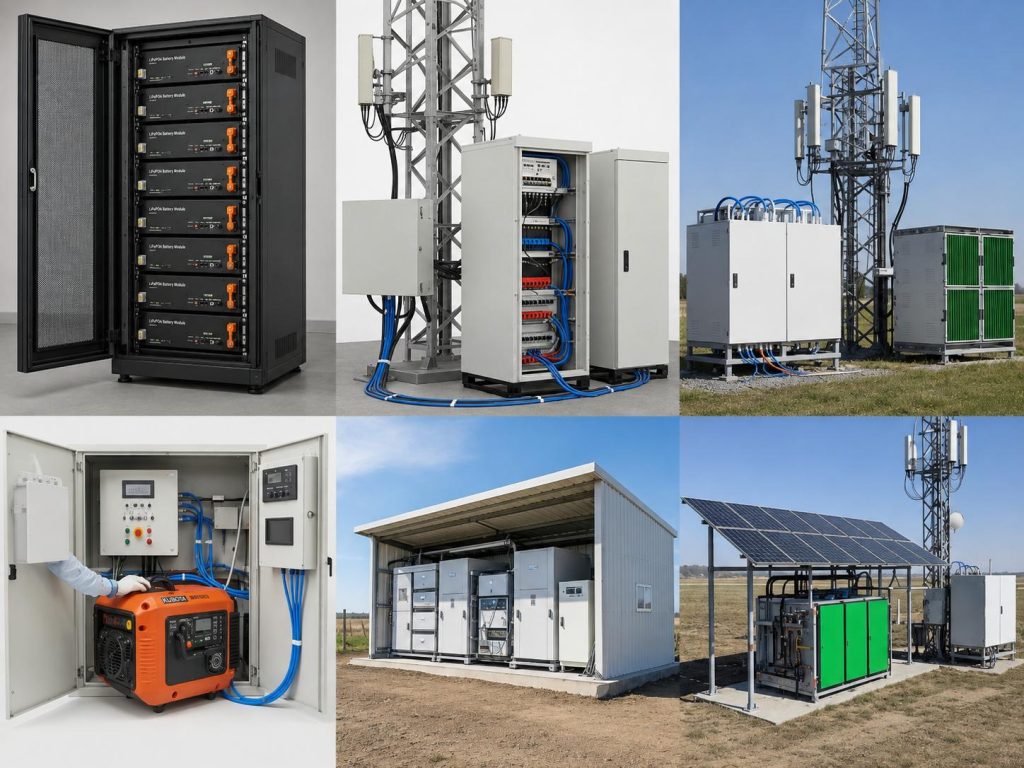
UPS and Battery Voltage Windows Must Be Matched
A common engineering mistake is:
48V UPS + 48V battery = compatible system
Nominal voltage is only a reference point.
A correct comparison should include:
| UPS Requirement | Battery Parameter to Verify |
| DC input range | Full battery operating voltage |
| Maximum DC current | Continuous battery/BMS current |
| Transient load demand | Peak current + duration |
| UPS low-voltage shutdown | BMS low-voltage cutoff |
| Required runtime | Usable battery energy |
| Communication | CAN/RS485 protocol compatibility |
VoltaLink’s 48V 150Ah rack battery is specified with an operating range of approximately 37.5–54V and 150A continuous discharge. Whether that configuration is suitable for a particular Data Center UPS Battery Backup depends on the UPS DC input window and required load current across that entire range.
High-Current Design Extends Beyond the Battery Cells
Once discharge current increases, installation hardware becomes part of battery performance.
Cable, connector, breaker, and busbar sizing should consider:
• Maximum continuous current;
• Short-duration peak current;
• Permitted voltage drop;
• Conductor temperature rise;
• Breaker trip characteristics;
• Short-circuit protection;
• BMS protection coordination.
This is why VoltaLink’s battery development approach includes PACK architecture, BMS integration, cell balancing, welding, modular assembly, and electrical testing rather than treating cell capacity as the only design parameter.
For a rack-based Data Center UPS Battery Backup, manufacturing consistency also matters. Variations between modules can become more visible when several batteries operate in parallel under high current.
High-Rate Performance Should Be Verified Separately from Safety Compliance
Safety certification and power capability answer different questions.
A battery may meet applicable safety requirements without automatically proving that it can support a particular UPS load profile.
For a serious Data Center UPS Battery Backup project, high-rate discharge curves, BMS thresholds, temperature derating data, peak-current duration, parallel limits, and operating-voltage behavior should be reviewed alongside relevant battery and UPS standards.
The final specification should therefore follow this sequence:
UPS Load → Minimum DC Voltage → Maximum Required Current → Battery/BMS Capability → Installation Losses → Parallel Architecture → Required Runtime
For VoltaLink, this is the practical value of treating cells, PACK structure, BMS logic, rack integration, and manufacturing consistency as one battery system. For data center UPS projects, providing the actual UPS DC range, critical load, desired runtime, and expansion plan allows VoltaLink to evaluate a rack-mount LiFePO₄ configuration around the real operating duty rather than simply selecting a battery by Ah.
FAQs
Q1. What type of battery does VoltaLink use for Data Center UPS Battery Backup applications?
For Data Center UPS Battery Backup applications VoltaLink utilizes the LiFePO₄ battery technology for rack-mount battery solutions. LiFePO₄ battery chemistry maintains steady discharge performance offering an extended service life coupled with superior thermal stability.
Q2. What are the main specifications of VoltaLink’s 48V rack-mount battery?
The 48V VoltaLink rack-mount battery has a rated capacity of 150Ah with an operating voltage range of 37.5V to 54V and a continuous discharge rating of 150A.
Q3. Can the VoltaLink 48V battery support high-rate UPS discharge?
The 150Ah module is rated for a continuous discharge of 150A. This is approximately a 1C discharge rate. The exact suitability is dependent on the UPS load, operating voltage, discharge time, temperature, and BMS constraints.
Q4. Can VoltaLink rack batteries be installed in standard server racks?
VoltaLink rack batteries can be installed in standard server racks. VoltaLink utilizes a rack-mount design that simplifies the installation of their rack-mount batteries for UPS, telecom, and data-center battery systems.
Q5. Can multiple VoltaLink batteries be connected in parallel?
VoltaLink rack batteries support modular parallel expansion. Parallel modules can increase installed energy and current while the maximum parallel capacity should be confirmed for each UPS system.

-

 OEM Residential Energy Storage Solutions: Passive vs. Active Cell Balancing
2026-09-30
-
 Smart Home Battery with BMS Communication: Cybersecurity and BMS Safety
 -
 10kWh Home Battery Backup System: Is 90% DoD Better for Daily Solar Storage?
2026-09-29
-
 Integrated Home Energy Storage System 150–430V MPPT Design
2026-09-28
-
 LiFePO₄ Residential Backup Battery SOC Accuracy in Parallel Systems
Share this:






.svg)






-899.svg)


