




Stackable Home Battery System BMS Architecture Explained
A Stackable Home Battery System is designed to make residential storage expandable, but adding battery modules is not simply a mechanical stacking process. Once several modules share the same DC bus, differences in state of charge (SOC), internal resistance, temperature, state of health (SOH), and wiring resistance can affect how current is distributed across the battery bank.
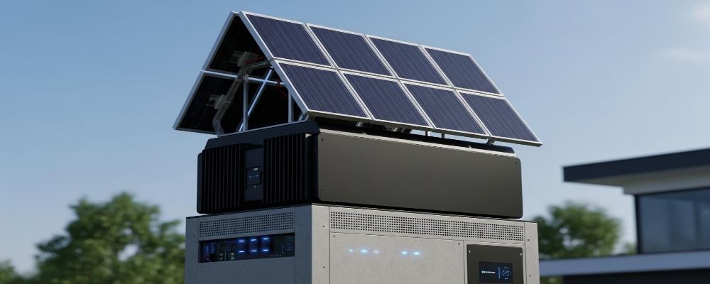
For this reason, the BMS in a Stackable Home Battery System must do more than protect individual cells. It must support coordinated operation between modules and provide the inverter with reliable system-level information.
VoltaLink’s 51.2V 400Ah system combines 20.48kWh LiFePO₄ storage, modular expansion, CAN/RS485 communication, integrated BMS monitoring, copper busbars, and natural cooling in a floor-standing architecture.
Why Parallel Battery Modules Do Not Naturally Share Load Equally
Two modules with the same nominal voltage are not electrically identical.
Parallel current distribution is dependent upon:
• Internal Resistance of cells and packs
• SOC and SOH differences
• Cell temperature
• Cable length and conductor resistance
• Busbar and connector resistance
• Manufacturing consistency
• Previous cycling history
If a module has a lower total resistance, it can initially draw more current than the adjacent modules. This can result in that module causing more heat build up and an accelerated accumulation of cycles, resulting faster in module-to-module imbalance.
This creates an important design principle:
Mechanical stackability does not automatically mean electrical synchronization.
VoltaLink addresses the consistency side of this problem by screening cells before integration and performing capacity, aging, and safety verification before shipment.
What the BMS Must Coordinate Across the Stack
In a multi-module Stackable Home Battery System, BMS coordination can involve several operating states.
| Control Variable | Why It Matters in a Multi-Module System |
| Cell voltage | Prevents individual cells reaching upper or lower limits first |
| Module current | Identifies abnormal current distribution |
| Temperature | Supports derating and thermal protection |
| SOC | Determines remaining usable energy |
| SOH | Helps identify aging differences between modules |
| Charge/discharge limit | Prevents the inverter demanding unsafe current |
| Alarm status | Allows coordinated system response to faults |
A useful distinction is that cell balancing and module synchronization are not the same function.
Cell balancing reduces differences between cells inside one battery pack. Module synchronization deals with complete battery units connected in parallel. Even perfectly balanced cells cannot compensate for unequal cable resistance, different module temperatures, or a large SOH difference between an old and a newly added battery.
Master-Slave and Distributed BMS Architectures Solve Different Problems
A Stackable Home Battery System may use centralized or distributed coordination.
| Architecture | Control Method | Engineering Trade-Off |
| Master-Slave | Module BMS units report to one system controller | Easier system-level aggregation, but the master becomes a critical node |
| Distributed | Modules exchange information across the network | Flexible scalability, but addressing and synchronization are more complex |
The purchasing question should therefore not be simply, “Does the battery have a BMS?”
More useful questions include:
• How is total system SOC calculated?
• How are modules identified on the communication network?
• What happens when one module loses communication?
• Can one faulty module be isolated?
• How are allowable charge and discharge currents communicated?
The exact control topology should be confirmed with the manufacturer rather than assumed from the word “stackable.”
CAN and RS485 Interfaces Do Not Guarantee Inverter Compatibility
VoltaLink’s Stackable Home Battery System supports CAN and RS485 communication for 48V/51.2V hybrid inverter integration.
However, matching the physical interface is only the first step.
CAN-compatible does not mean compatible with every CAN inverter.
System integration should verify:
• Communication protocol
• Connector pin definition
• Inverter model and firmware
• BMS firmware
• SOC reporting format
• Charge-current limit
• Discharge-current limit
• Warning and fault messages
Closed-loop communication is preferable where supported because the BMS can continuously send allowable current limits to the inverter. Instead of waiting for an overcurrent or undervoltage protection event, the inverter can reduce power before the battery reaches a hard protection threshold.
VoltaLink develops key system components including BMS, EMS, PCS, and hybrid inverter technologies in-house and also provides BMS customization, which gives system integrators additional scope for protocol and project-level matching.

Adding More kWh Does Not Automatically Add More kW
The VoltaLink configuration is rated at:
51.2V × 400Ah = 20.48kWh
This describes stored energy—not maximum discharge power.
Available power depends on the entire DC current path:
Cells → BMS → Busbar → Connector → Cable → Inverter
For example, at 51.2V:
• 100A is approximately 5.12kW DC
• 200A is approximately 10.24kW DC
Therefore, expanding a Stackable Home Battery System increases energy capacity only within the current and power limits of the BMS, conductors, connectors, inverter, and protection devices.
The VoltaLink product page lists a 10kW rated AC side with 20kW surge capability, so system designers should verify that the selected battery configuration, inverter, and DC current limits are correctly matched for the required load.
Expansion Requires Controlled Commissioning
A new battery module should not be connected to an existing stack solely because both units are rated at 51.2V.
Before parallel expansion, installers should verify:
• Battery voltage and SOC
• Capacity and SOH
• Cycle history
• Firmware compatibility
• Communication settings
• Cable length and conductor size
• Connector and busbar condition
• Temperature and ventilation
A voltage difference between two low-resistance parallel batteries can produce a significant equalization current when they are first connected.
Older and newer modules also deserve special attention. Differences in usable capacity and internal resistance can cause the older unit to reach a voltage limit earlier, restricting the usable energy of the complete Stackable Home Battery System.
BMS Protection and Safety Certification Are Different Layers
BMS functions such as overcharge, over-discharge, overcurrent, short-circuit, and thermal protection are important, but they are not substitutes for system-level safety verification.
For residential ESS procurement, buyers may need to assess:
• IEC 63056 for lithium batteries used in energy storage systems
• UL 1973 for stationary battery applications
• UL 9540 for complete energy storage systems
• UL 9540A for thermal runaway propagation testing
• UN 38.3 for lithium battery transport
Certification should always be checked against the exact model and system configuration, not inferred from a manufacturer’s general certification portfolio.
What Buyers Should Verify Before Approving a Stackable Home Battery System
Before procurement, request technical confirmation of:
• Maximum supported parallel configuration
• Continuous and peak BMS current
• Balancing method and balancing current
• Supported inverter protocols
• SOC/SOH management method
• Fault isolation strategy
• Expansion requirements for new modules
• Cycle-life test conditions
• Applicable certification documents
A reliable Stackable Home Battery System is therefore not defined by kWh alone. Long-term scalability depends on cell consistency, BMS coordination, controlled current sharing, inverter communication, thermal design, and disciplined expansion procedures.
VoltaLink combines LiFePO₄ PACK manufacturing with BMS, inverter, EMS, and PCS development, allowing residential storage projects to be evaluated as complete electrical systems rather than isolated battery modules. For projects requiring 51.2V modular storage, future capacity expansion, and inverter integration, buyers can review the technical configuration of the VoltaLink 51.2V 400Ah Stackable Home Battery System and discuss project-specific BMS and system requirements with its engineering team.
FAQs
Q1. What is the capacity of VoltaLink’s Stackable Home Battery System?
VoltaLink’s featured Stackable Home Battery System is rated at 51.2V, 400Ah, and 20.48kWh, using LiFePO₄ battery chemistry for residential energy storage.
Q2. Does VoltaLink’s Stackable Home Battery System include a BMS?
Yes. The system integrates an intelligent BMS that monitors important operating parameters such as battery voltage, current, and temperature.
Q3. Can the VoltaLink Stackable Home Battery System be expanded later?
Yes. The system uses a modular stackable architecture designed for parallel capacity expansion. The exact supported configuration should be confirmed according to the project and inverter setup.
Q4. How does VoltaLink improve consistency between battery modules?
VoltaLink applies cell consistency screening before battery integration and performs capacity, aging, and safety verification to reduce variation between cells and modules.
Q5. Does the Stackable Home Battery System support CAN and RS485?
Yes. VoltaLink supports CAN and RS485 communication, allowing the battery BMS to exchange operating data with compatible 48V/51.2V hybrid inverter systems.

-

 OEM Residential Energy Storage Solutions: Passive vs. Active Cell Balancing
2026-09-30
-
 Smart Home Battery with BMS Communication: Cybersecurity and BMS Safety
 -
 10kWh Home Battery Backup System: Is 90% DoD Better for Daily Solar Storage?
2026-09-29
-
 Integrated Home Energy Storage System 150–430V MPPT Design
2026-09-28
-
 LiFePO₄ Residential Backup Battery SOC Accuracy in Parallel Systems
Share this:





.svg)






-899.svg)


